The Theory of Meccano Gears: Part 1 — Spur Gears
Written by Alan Wenbourne in June 2021
Introduction
Gearing is sometimes regarded as a ‘black art’, or at least an abstruse subject. Like most technical subjects, it can become very complex, especially when dealing with multi-dimensional curved surfaces described by mathematical or geometric laws of curves, such as used in the design of spiral, hypoid and spiroid gears for instance. However, for the straight-cut Meccano spur gears, there should be no reason for not designing them to a coherent ‘system’ and producing them to normal standards.
In Meccano publications that I have read there have been some suggestions that Meccano gears are not of involute form — that some gears are ‘peculiar’, ‘pointed’ or at least produced by experimental methods. Not having any inside knowledge of how Meccano gears were or are made, I prefer to assume that they were designed and manufactured using gear technology and well established engineering practice and principles. My examination and measurement of Meccano gears over the years supports the above assumptions, also indicating that they conform to a British Standard Specification (see reference 1), notwithstanding a few poor quality or improperly finished gears.
I would like to present and share my experience and understanding of Meccano gears in this series of articles, starting with the basics in applying gear theory and practice to the Meccano range of spur gears. I have no knowledge of other Meccano look-a-like systems, so these are not considered.
A spur gear is one having straight teeth formed on a cylindrical surface, parallel to the axis of rotation. They are used to transmit drive across parallel shafts. Figure 1 shows a typical Meccano spur pinion (1) and spur gear (2).
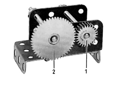
Figure 1 Spur pinion and spur gear
I use the noun ‘gear’ as a generic term and also, as in Meccano terminology, for the larger of a pair of mating gears. Where necessary, to distinguish the difference, I use the term ‘pinion’ for the smaller gear.
A gear is merely a continuously rotating lever in the form of a cylinder, with bumps, pegs, pins or teeth applied to the surface to prevent slipping. For maximum rolling efficiency, formed teeth have proved successful.
Many geometric curves, or forms, have been considered and applied, but the involute form has become the most popular tooth profile, satisfying efficiency and ease of manufacture.
Gears are made using a multitude of methods such as forging, stamping, rolling and machine cut by shaping, hobbing, shaving and grinding etc. For the purpose of this article, I refer to machine cut methods, since these help explain the flexibility of the generated involute tooth form.
Gear tooth features and terminology need to be considered in the explanation and understanding of this fascinating subject. Often standard values or ranges are adopted for reasons of standardisation of tooling, interchangeability, ease of manufacture, convenience, proven good tooth meshing action or strength and wear durability. However, standard proportions are by no means strict rules, as, in particular industries, departure from these can produce optimum advantage in application.
There is no particular order of preference in selecting and defining gear geometric variables in the design process — this may depend on the application and specific requirements, such as if the gear is to ‘fit’ within an existing dimensional system or constraint, if it is required to satisfy a particular ratio requirement, if it is required to operate at high speed or load, if it is required to meet low noise emission, or if it is to satisfy high levels of safety or reliability etc. Any of these requirements may define some of the starting parameters of gear design. Fortunately, not all are important or necessary in the design of Meccano gears.
Spur Gear Proportions, Definitions and Terminology
In the following nomenclature, upper case letters (A…Z) refer to the gear and lower case letters (a…z) to the pinion. Where functions can apply to both, I have referred only to the gear. Common abbreviations are shown in curly brackets {}, followed by any mathematical nomenclature applicable in parenthesis (). The equations are numbered in square brackets [] for further reference.
Figure 2 shows the definitions used.
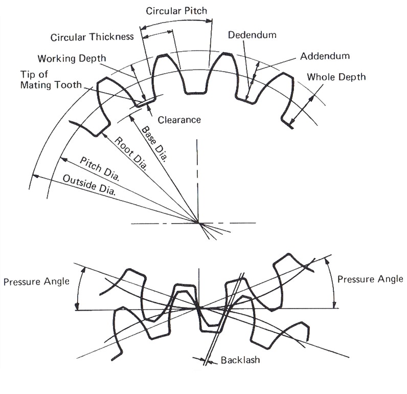
Figure 2 Spur gear definitions
The usual order of selecting and defining gear design variables is as follows (with some reasoning, although advanced reading may be necessary to identify all variables):
Pitch Circle {PCD} (D)
This is the diameter of a circle about which the gear tooth geometry is constructed. In gears having standard proportions, it is known as the standard pitch circle and represents the imaginary circles or cylinders of each gear in rolling tangential contact, their diameters being in direct proportion to the number of teeth in each gear respectively and hence the gear ratio.
D = N / P [1]
Operating Pitch Circle (De)
Sometimes standard proportions cannot be adhered to. In this case the gear tooth may be ‘shifted’ from its relationship with the standard pitch circle. Then a new imaginary ‘operating pitch circle’ is established, which has the same tangential contact with the operating pitch circles of its mating gear(s) and as before, the same relationship to tooth numbers and ratios.
De = 2N / (N + n)Ce [2]
Ratio (R)
In designing gear drives, the speed or torque relationship between the driven and driving shafts is generally known, or at least target values are estimated. The required ratio is then expressed as the output speed divided by the input speed in relation to unity.
This ratio is then used to determine the gear sizes in terms of pitch circle diameters using:
R = D / d [3a]
or:
D = Rd [3b]
or:
d = D / R [3c]
Pitch
The pitch of gear teeth is a measure of their distance apart around the pitch circle. It is expressed in the following forms:
Diametral Pitch {DP} (P)
The number of teeth per inch of diameter.
P = N / D [4a]
or:
D = N / P [1]
or:
N = PD [4b]
Module {Metric Pitch} (m)
The number of millimetres diameter per tooth.
m = D(mm) / N [5a]
or:
D = mN [5b]
or:
N = D / m [5c]
Circular Pitch {CP} (p)
The distance measured around the pitch circle from one tooth to the next.
p = πD / N [6a]
or:
D = pN / π [6b]
or:
N = πD / p [6c]
Some useful formula for expressing one pitch system in terms of another are:
p = π / P = πm / 25.4 [7a]
P = π / p = 25.4 / m [7b]
m = 25.4p / π = 25.4 / P [7c]
For our purposes we will use diametral pitch, as this is the known basis of proportioning Meccano spur gear teeth, i.e. 38 DP (P = 38).
However, Meccano spur gears are: 0.08267” circular pitch (from equation 7a), or 0.66842 metric pitch module (from equation 7c).
Number of Teeth (N or n)
The number of teeth in the gear (N) or pinion (n), where:
N = DP [8a]
and:
n = dP [8b]
If these are integers, then the gears will have standard proportions. As is more likely, they will have decimal (or fractional) values, and then standard values may be derived by adjusting the pitch diameters to the nearest integer tooth values.
To do this, new pitch diameters are calculated using the nearest integer values to N and n above, i.e.
D = N / P [9a]
and:
d = n / P [9b]
This will compromise the centre distance and the ratio. If this compromise is not acceptable, then more trial iterations are made in an attempt to satisfy the important parameters, otherwise non-standard proportions may be used (more about this later).
Of course, the choice of values for N and n may also be driven by the ratio requirements when:
R = N / n [10a]
or:
N = Rn [10b]
or:
n = N / R [10c]
Base Circle (Db)
The base circle is a circle of diameter equal to the cosine of the pressure angle times the pitch diameter, i.e.
Db = Dcos y [11]
From which the involute curve forming the tooth profile is generated.
Involute
The involute curve is generated by the locus of a point on a piece of string or cord (for example), when un-wound from a cylinder equivalent in diameter to the base circle (see figure 3).
A part of this involute curve forms the gear tooth profile between its junction with the root radius and the gear outside diameter.
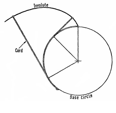
Figure 3 Involute curve generation
Line or Path of Action
An imaginary line tangent to and joining the base circles of a pair of mating gears (see figure 4). It is the line along which the point of contact passes, as a pair of teeth enters and leaves mesh. It can also be considered as a cord, wrapped around both base circle cylinders, transmitting drive from one to the other.
Pitch Point
The point at which the line of action intersects a line passing through the axes of both gears (see figure 4).
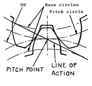
Figure 4 Pitch Point and Line of Action geometry
Pressure Angle {PA} (y)
The pressure angle is the angular deflection of the line of action normal to the centreline through the gear axes. For standard cut gears it is also the pressure angle of generation (PA of cutter). It can be varied to alter the tooth contact conditions (contact ratio) or tooth bending strength.
A typical value is 20°, a standard value for which a tremendous amount of tooling exists in the gear manufacturing industry. A smaller angle increases contact ratio and decreases strength, a larger pressure angle has the converse effect.
Early gears used a 14½° pressure angle, mainly because the sine of 14½° is very nearly ¼, which made calculations easier before the advent of electronic calculators.
25° PA is sometimes used for increased tooth strength at the expense of higher tooth separating loads. The pressure angle can be any practical value to satisfy specific requirements or special purpose gearing.
Some time ago I was able to examine a selection of Meccano gears using an engineering inspection machine called a shadowgraph. This machine produces sharp edge magnified images, projected onto a screen for comparison with templates. I made a template of a 57-tooth gear tooth profile 20 times full size and compared it with the projected image of an actual Meccano gear. The result confirmed to me that the Meccano gear was of involute form having a 20° pressure angle (also conforming with reference 1).
Operating Pressure Angle (ye)
The same as above for standard gears, but different for gears designed to work at extended or contracted centre distances.
The operating pressure angle can be calculated from the following equation if standard PCD’s, pressure angle of generation and extended centre distance are known:
ye = arc cos[(D + d)cosy / 2Ce] [12]
Centre Distance — Standard (C)
This is the distance between the operating centres of a pair of mating gears. It can be calculated from:
C = (N + n) / 2 / P [13]
Centre Distance — Extended (Ce)
When a pair of gears are required to operate at a pre-determined centre distance, gears designed to standard proportions will not always ‘fit’ that centre distance. In this case, it is usual to choose standard pitch and tooth number proportions (to satisfy, or approximate the required ratio), which fall close to, but less than, the target centre distance. Then, the involute profile of one or both gears is shifted, so as to operate at the ‘extended centre distance’.
This procedure is normal and very important in designing gears around standard tooling. Applying positive displacement to the involute profile (shifting it radially outwards) has the advantage of thickening the tooth at its root, providing additional strength.
Gears can also be designed to work at ‘contracted (or closed) centre distance’ — this applies when a pair of gears with particular tooth numbers are needed, but the calculated standard centre distance is greater than that required.
In this case one or both of the gears are cut with negative profile shift, i.e. the teeth are thinned to allow closer than standard meshing centres.
Examples of Meccano gears cut with standard, positive and negative profile shift, using the centre distance equation 13, are illustrated as follows:
(19 + 57) / 76 = 1”
(19 + 95) / 76 = 1.5”
(19 + 133) = 2”
(38 + 38) / 76 = 1”
These are cut to standard tooth thickness (less backlash allowance of course).
(25 + 50) / 76 = 0.9868”
(15 + 60) / 76 = 0.9868”
(30 + 45) / 76 = 0.9868”
These combinations require positive profile shift (centre distance extension) to mesh at 1.00” centres, although the small difference in calculated centre distance of 0.013” (equivalent to approximately 4.4 thou’ backlash) may equate to the amount of thinning for backlash required.
(22 + 55) / 76 = 1.013”
(11 + 66) / 76 = 1.013”
(13 + 65) / 76 = 1.0263”
These combinations require negative profile shift (centre distance contraction) to mesh at 1.00” centres.
A commercial alternative is to optimise the pitch to a non-integer, non-standard value which may require special cutters or tooling for manufacture. This would be an entirely acceptable solution for moulded or stamped gears for instance, or for a pair of gears not part of a ‘system’ requiring interchangeability of gears of different sizes, or if producing special cutters for machine cutting were economically viable.
Circular Tooth Thickness (t)
This is the tooth thickness measured around the pitch circle diameter (circular measure), between the points where the involute curves cross the pitch circle diameter. It follows therefore, that if the circular tooth thickness is the same as the circular tooth space (no backlash), then the sum of the tooth thicknesses and tooth spaces equal the pitch circle circumference, leading to the expression:
t = pD / N / 2 = p / 2 / P [14]
The tooth thickness is an important variable in modifying gear teeth to meet the requirements of non-standard operating conditions. Probably the most practical purpose for varying the tooth thickness is ‘thinning for backlash’. In this instance, the gear tooth cutter is ‘fed-in’ more than is required to produce the standard thickness, which generates a thinner tooth to provide running clearance, or ‘backlash’.
The thinning for backlash can be applied to one or both gears of a mating pair. When applied to both, the allowance is shared between the two (not necessarily equally).
Sometimes all the thinning for backlash is removed from one gear of a pair, usually the wheel. This is done for better balancing of tooth strength, because the larger gear (wheel) has wider teeth at the root and lower tooth mesh frequency than the pinion.
Addendum (a)
The radial height of a gear tooth above the standard pitch circle. Its value is:
a = 1 / P [15]
Outside Diameter {OD} (Do)
The diameter of a gear over the tips of its teeth. Sometimes referred to as the ‘major’ diameter. The standard OD is:
Do = D + 2a [16]
This standard OD is usually the size of the gear blank, prior to cutting the teeth. The OD can be made non-standard within certain limits. A larger OD increases contact ratio, smaller (sometimes referred to as ‘topping’ the teeth) reduces contact ratio, but may be desirable for providing clearance to adjacent parts.
Dedendum (d)
The radial depth of a gear tooth below the standard pitch circle. This is greater than the addendum to allow for clearance of the tips of the mating gear teeth to the root radius, or fillet form. It varies, in standard form, dependant upon the cutting method.
My measurements of Meccano gears indicates their conformance with reference 1, which is:
d = 1.4 / P [17]
When the cutter is displaced for a non-standard gear, the dedendum varies accordingly.
Whole Depth of Tooth (h)
The radial height of a gear tooth between the root and outside diameters. Also controlled by cutter proportions and depth of cut. The standard whole depth is:
a + d
or:
h = 2.4 / P [18]
Root Diameter (Dr)
The diameter measured between the tooth root fillet radii, sometimes referred to as the ‘minor’ diameter. This is a function of the depth of cut produced by the cutter. The cutter will be proportioned to satisfy the dedendum requirements. The standard root diameter is:
Dr = D − 2.8 / P [19a]
or:
Dr = Do − 4.8 / P [19b]
Fillet Radii
The radius or radii in the tooth root between the involute flanks and below the active profile. This is made as large as possible for increased tooth bending strength and minimum stress concentration.
Active Profile
That part of the tooth involute flanks over which the point of contact passes.
Tooth Flank
The contacting faces of gear teeth.
Backlash
The shortest distance (gap) between the involute flanks of a mating pair of gears on the non- contacting flanks (the running clearance).
Face Width {FW}
The axial width of a gear at the toothed portion.
Contact ratio {CR}
The amount that sequential tooth meshes overlap. For smooth, quieter operation, more than one tooth must be in contact with teeth of the mating gear.
Typical values are 1.1 to 1.8. It can be increased by modifying the addendum (long addendum).
Spur Gear Design
My ‘spurgearcalc’ spreadsheet below is based on the analyses used in reference 2, and was used to confirm the theory and conclusions I reached in this study and measurement of Meccano gears.
Download the spurgearcalc spreadsheet in Microsoft Excel format.
Notes Regarding 40DP Meccano Gears
There is a school of thought that Meccano gears may have been cut with 40DP cutters (see reference 3). The argument being that the Meccano worm is in fact a 9/16” Whitworth thread (BSW), this being 12 teeth per inch (TPI) as is the worm. Meccano racks are also 12TPI. 38DP is 0.08267” circular pitch, 40DP is 0.07854” circular pitch and 12TPI is 0.08333” pitch. The pitch difference between 38DP and 12TPI is: 0.00066” (very small). The pitch difference between 40DP and 12TPI is: 0.00479” (significant).
Reference 1 proposes that 38 teeth were cut on a 1.00” PCD using 40DP geometry to minimize the pitch difference between 40DP and 12TPI because, by doing so the circular pitch is 0.08267” (as with the 38DP cutter), thereby claiming that Meccano gears are a thread-based, not a gear-based system?
The ‘standard’ pitch diameter for 38 teeth cut on a 1.00” PCD with a 40DP cutter is 0.95”, therefore the cutter has to be ‘withdrawn’ so as to cut the 38 teeth on an 1.00” PCD, thereby facilitating correct meshing conditions for two such gears operating at 1.00” centre distance. This cutter withdrawal displaces the involute profile radially outwards and is termed ‘profile shift’.
Using the 38-tooth gears P/N 31 as an example, I am trying to prove mathematically and by measuring my gears that they may have been made to 40DP proportions.
Profile shifting (outward) increases pressure angle, which can have the visible effect of making the teeth more pointed (less crest width), but since the 40DP cutter is a finer pitch than 38DP, this effect may be less noticeable. Also, a 40DP tooth is less deep than a 38DP tooth, but the difference is only: 0.003” — not obvious, difficult to measure, and lost within normal manufacturing tolerances anyway!
The outside diameter differs also by only 0.003”, which again, would be lost within the normal manufacturing tolerance. In any case, the OD is relatively unimportant and variable because it is merely the initial blank size (ignoring the effect of blank diameter on contact ratio).
Thus, for two 38-tooth gears, one cut with 38DP, the other cut with 40DP cutters, the difference would be very difficult to differentiate visually or even by measuring their features. This leaves determining the actual position of the involute tooth flanks as the most likely indicator of differing manufacturing methods.
One method of determining the involute position is to calculate the measurement over pins of known size, placed between teeth on opposite sides of the gear, and to compare this with actual measurements. Hence the mathematical/measured comparisons in chart 1, which assume 20° pressure angle and 0.4”/DP root clearance (an industry standard). ‘Theory’ denotes calculated values. ‘Actual’ denotes measurements taken from a sample of six gears.
From this evidence, the measurement over pins and crest width figures indicate that these gears were made using 38DP rather than 40DP cutters!
Further study of 20-tooth pinions assuming 38 and 40DP generation is summarized in chart 2. This evidence supports the 40DP theory.
It would be easy to accept the obvious that early 20-, 25-, 40- and 50-tooth gears were cut to 40DP standard, as the pitch diameters calculate exactly to the ratios (standard gears). However, the 56-tooth gear does not conform?
40DP either produces 60 teeth on a 1.5” PCD, or a PCD of 1.4” for 56 teeth! So the 56 teeth are profile shifted to 1.5” PCD (at 40DP), but then the crest width would be only 0.006”! Whereas my samples measure at least 0.015”?
Pin measurements merely indicate the radial position of the tooth flank at their point of contact. To determine the shape of the gear tooth profile by this means would require a number of pin measurements in order to plot the polar and radial co-ordinates of the curve. This would be very tedious and time consuming, which is why specialised equipment exists for this purpose such as shadowgraphs and involute checking machines.
Other factors that detract from this kind of analysis are the (unknown) design intent, manufacturing tolerances, and wear of the sample gears being measured.
Notwithstanding all these limitations, I conducted the same analysis of 19- and 57-tooth gears, taking three sets of measurements each from three of each gear; the data are shown in chart 3. These results are clearly in favour of 38DP proportions.
Could it be that the early gears approximated to 40DP but were not involute in profile?
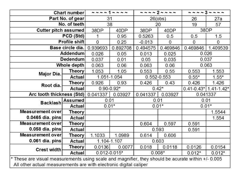
Charts 1–3: Calculated and measured data for Meccano gears (dimensions in inches)
Conclusions
- The original (obsolete) 20-, 25-, 40-, 50- and 56-tooth gears could have been made to 40DP proportions, however:
- It is more likely that they were cut to 0.65” module (39.07DP) of double circular arc form similar to BS 978: Part 2 — Gears for Instruments and Clockwork Mechanisms. Although these gears (1903–1920) pre-date the British Standard, the standard would have incorporated the practice of clockmakers up to the time of compilation/publication. It is known that Hornby used clockmakers to produce early gears.
- According to my measurements and calculations, the 19-, 38-, and 57-tooth series conform to 38DP.
- One would hope that replica, reproduction and compatible gears would conform similarly.
- Meccano gears conform to a gear system rather than a thread standard.
- It is possible to mix and mesh the obsolete 40DP gears with the later 38DP gears because the size and pitch differences are small, compared to the backlash and clearance allowances adopted in their manufacture.
- The Meccano worm does indeed appear to conform to 9/16” BSW proportions at 12TPI, also by having an included angle of 55°. The root diameter at 0.44” (0.4558”-BSW) and outside diameter of 0.554” (0.5625”-BSW) are slightly undersize, probably to reduce the effective diameter of 0.509” (BSW) to the ½” Meccano standard. Therefore it appears that the worm and racks are based on the 12TPI BSW thread system and the 0.00066” pitch is insignificant.
Working Centres and Ratios
Sometimes we need a ‘special’ ratio, which can be achieved by meshing gears not normally paired together. This invariably involves a non-standard centre distance to achieve the correct mesh conditions.
There is always some scope for variation of the true centres due to backlash and running clearances, but chart 4 shows the theoretically correct working centre distances for all combinations of Meccano and compatible gears.
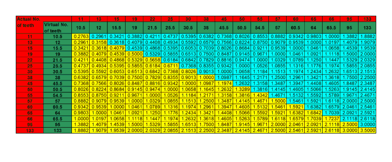
Chart 4: Working centres for Meccano and compatible gears (dimensions in inches)
If any pair of gears do not run efficiently at these centre distances, it could be due to manufacturing errors or excessive tolerances adopted in their production — I have, for example, some oversize 22-tooth pinions and undersize 2½” ring gears.
The virtual (see explanation below) numbers of teeth are those used to calculate the working centre distance from the formula:
CD = (T + t) / 2 / DP [20]
where CD is the centre distance, T and t are the number of teeth in the gear and pinion respectively, and DP the diametral pitch (38). Chart 5 is a quick reference of the gear ratios for all combinations of tooth numbers.
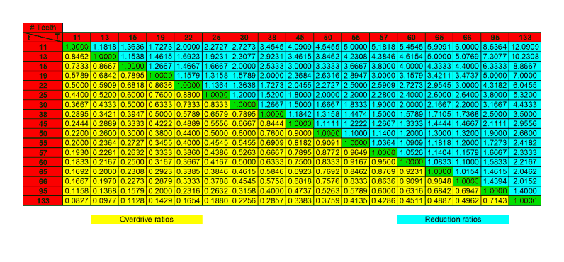
Chart 5: Gear ratios for Meccano gears (T / t)
I use the term ‘virtual’ because some gear tooth numbers do not compute correctly for 38DP. For example, for the 60-tooth/15-tooth combination giving a ratio of 4:1, the operating pitch circle diameters are 1.6” and 0.4”. However, at 38DP, these tooth numbers indicate standard PCD’s of 0.3947” and 1.5789” respectively! Still 4:1, but the sum of the pitch circle radii is 0.9868”, which is 0.0132” short of the required 1.000” working centre distance. Alternatively, the 0.4” and 1.6” PCD’s at 38DP indicate tooth numbers of 15.2 and 60.8!
This situation is overcome by extending the standard centre distance from 0.9868” to 1.0000” and is achieved by shifting the involute profile of each gear radially outward. Then 15 and 60 teeth are cut on the extended PCD’s (+0.01055” and 0.00265” profile shift per gear respectively).
By this means, 15-tooth and 60-tooth gears are made using 38DP tooling that mesh correctly at 1” centre distance. Other apparently non-standard gear ratios such as the 11/66, 22/55, 25/50 and 30/45 combinations are also produced using negative or positive profile shift.
Another way to treat this situation is to consider that one tooth must be lost from the pair (15.2 + 60.8) − 75 = 1), then by using a ‘virtual’ pitch of 37.5DP (half a tooth less per gear), the PCD’s calculate correctly. Similarly, by adding half a tooth to each gear, giving ‘virtual’ numbers of teeth of 15.5 and 60.5, then at 38DP, the centre distance calculates correctly.
Note: This virtual analogy is an expedient for the above chart only and should be treated with caution; it does not apply to individual gears and the actual pitch of a gear is determined by the cutter or tooling.
Meccano-Compatible 30DP Gears
Chart 6 is a ratio selection chart for the range of 30DP gears produced by Tony Bolton.
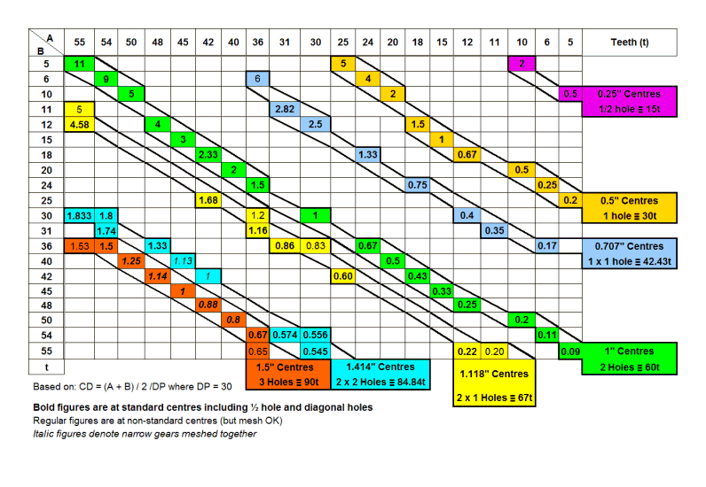
Chart 6: Ratio selection chart (A / B) for Tony Bolton Meccano-compatible 30DP gears
References
- British Standards Institution. British Standard BS 978:1952, Part 1 — Gears for Instruments and Clockwork Mechanisms.
- H. E. Merritt. Gear Engineering. Pitman & Company, London, 1971.
- Fraser, Neil. “Diametral Pitch.” Neil’s News, 3 April 2004, neil. fraser. name/news/2004/04/03. Accessed 1 June 2021.
This article combines elements from articles previously published in 2006, 2007 (Gear Design; Notes Regarding 40DP Meccano Gears; Working Centres and Ratios) and 2011 (Meccano-Compatible 30DP Gears).
See also parts 2 and 3 of this series covering helical gears and bevel gears.