The Theory of Meccano Gears: Part 2 — Helical Gears
Written by Alan Wenbourne in June 2021
Introduction
Presumably helical gears were introduced into the Meccano system to provide an alternative crossed axis drive system to the worm gear and in response to requests for a skew gear in the system. Also, helical gears can be ‘back driven’, whereas single start worm gears generally cannot be.
The original Meccano helical gears, shown in figure 1, were in the form of the 14-tooth and 35-tooth gears, parts 211a and 211b, giving a reduction ratio of 2.5:1 — a much smaller numerical ratio than usually obtained with a worm and wheel.
Licensed and reproduction Meccano specialists have added to the available range of compatible helical gears.
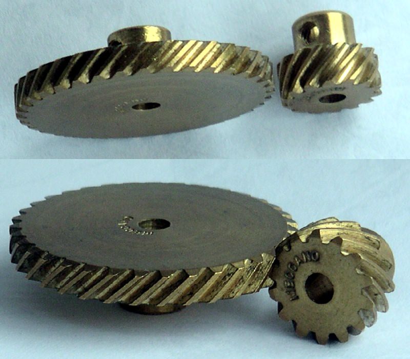
Figure 1 Meccano helical gears, parts 211a and 211b
General Principles
Helical gears have teeth cut at an angle to their cylindrical axis, as opposed to spur gears having so called ‘straight cut’ teeth (parallel to their axis).
The teeth can be envisaged as a spiral running around a cylinder and can be left or right hand helices (direction of wind), rather like a ‘quick’ screw thread as opposed to the normal screw thread or worm gear. The helical angle can vary according to the application requirements.
The Meccano helical gears (parts 211a and 211b) have a helix angle of 45° and are both right hand helices. This means that they will mesh on axes at 90° to each other (crossed axes). Gears having the same helix angle but of opposite hand can be meshed together on parallel axes.
The commercial advantages of helical gears are that the teeth are stronger than the equivalent spur gear due to the longer and thicker (in the plane of rotation) tooth form and they run quieter owing to the additional contact ratio achieved through the helical overlap.
The helix angle of parallel axis gearing is generally less than 20° and is determined by the facewidth and the degree of overlap required. Otherwise the helix angle can be set to create gears that mesh on axes at any angle.
The disadvantage of helical gearing is that axial thrust is created, the magnitude of which depends upon the helix angle, and this thrust load has to be borne by the bearings and mounting arrangements. Also, in non-parallel axis helical gearing, sliding friction is significant.
The direction of thrust created by the helical action depends upon the direction of rotation and the hand of the helix. There are too many variations and arrangements of helical gears to describe the thrust direction, but it can easily be assessed by imagining the helix of the driver as a screw thread and the direction of the resultant axial thrust this would produce on the drive shaft. Similarly, the reactive thrust direction on the driven shaft can be determined. In reversible drives, the thrust will act in both directions.
Helical Gear Proportions, Definitions and Terminology
Compared to straight spur gears, most of the proportions of helical gears are modified by the helix angle. For example, for a given pitch, all the radial proportions and centre distances of helical gears are larger by a function of the helix angle. Tooth proportions and functions can be described in terms of the normal pitch (at right angles to the tooth) or transverse (in the plane of rotation).
Figure 2 shows definitions for the helical gear (reference 1).
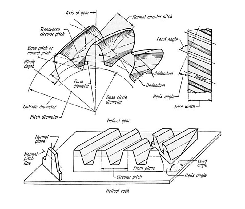
Figure 2 Helical gear definitions
The influence of the helix angle on the radial proportions of a helical gear render it more difficult to obtain exact or integer values of pitch diameter and centre distance, for example. If a specific pitch diameter and/or centre distance is required, involute profile shifting or a compromise helix angle can achieve them.
The latter provides the designer some flexibility in achieving specific pitch diameters or centre distance by making the helix angle the variable in the calculations. Thus, the helix angle need not be an integer figure, but the required fractional/decimal value dictated by other parameters.
Because the helix angle increases the pitch diameter (relative to straight spur gears), for a given centre distance the equivalent helical gear is courser in pitch.
In the case of Meccano spur gears, where 38DP equates to 1” centre distance, for the 45° helicals (parts 211a and 211b), the pitch is 35DP.
In the following nomenclature, common abbreviations are shown in curly brackets {}, followed by any mathematical nomenclature applicable in parenthesis (). The equations are numbered in square brackets [] for further reference.
Helix Angle (σ)
This is the angle the involute tooth form makes with the transverse plane (plane of rotation) at the pitch radius.
Diametral Pitch {DP} (Pn)
This is the pitch normal (at right angles) to the tooth. It can be expressed in Module or Circular terms, also in the Transverse plane.
Direction of Helix (RH or LH)
The direction of wind of the helix. Can also be expressed as Lead, the axial advance of the tooth in one revolution (as in thread pitch).
Pitch Circle {PCD} (D)
The standard pitch circle diameter is given by:
D = N / Pn / cos σ[1]
Operating Pitch Circle (De)
The effective rolling diameter.
De = 2NCe / (N + n)[2]
Pressure Angle {PA} (ψn)
The pressure angle normal to the tooth. This is usually the pressure angle of the cutter (of generation).
Transverse Pressure Angle (ψt)
The pressure angle in the plane of rotation at the standard PCD. (Note: Helical gear teeth appear thicker in this plane than in the ‘normal’ plane.)
Ψt = arc tan(tan ψn / cos σ)[3]
Centre Distance — Standard (C)
C = (N + n) / cos σ / 2 / Pn[4]
Centre Distance — Extended (Ce)
The intended operating centre distance — extended or contracted standard centre distance.
Addendum (A)
A = 1 / Pn[5]
Outside Diameter {OD} (Do)
Do = D + 2A[6]
Dedendum (B)
Assuming the same root clearance of 0.4 / P as for straight Meccano spur gears.
B = 1.4 / P[7]
Whole Depth of Tooth (h)
h = A + B[8]
Root Diameter (Dr)
Dr = D – 2B[9]
Contact Ratio (Cr)
This is the sum of the involute tooth overlap and the helical overlap, hence a higher value than can be achieved with straight spur gears.
Profile Shift (k)
The amount the involute profile is displaced radially from standard. It can be applied to straight spur gears to meet specific operating conditions. It is invariably applied to helical gears for the same reason and to compensate for the radial shift created by the helix angle.
Helical Gear Design
The design of helical gears involves complex calculation to determine the optimum geometry, operating conditions and inspection measurements.
Attempting to ‘reverse engineer’ a pair of gears without any knowledge of the original design intent or manufacturing methods is fraught with difficulties.
Gears may be initially designed in accordance with established standards and commercial practice, when a technical specification is drawn-up in the form of a working drawing. Such gears would be designed around available machinery and cutters, or maybe special cutters manufactured for the purpose — usually very expensive. Or they may be ‘created’ in a prototype workshop using available cutting tools and equipment, with the overall proportions established by trial and error. When the desired proportions are established, they, the machine settings and the tooling geometry would be recorded for future reference and manufacture of further batches.
It is probable that the design and conception of Meccano helical gears falls somewhere in-between the two extremes mentioned above. Thus, not being aware of the design or manufacturing philosophy, some assumptions have to be made.
I have assumed that the Meccano helical gears conform to standard gear design practice and manufacture for machine cut gears.
My ‘helicalgearcalc’ spreadsheet below is an analysis of the 14-tooth and 35-tooth Meccano helical gears (parts 211a and 211b).
Download the helicalgearcalc spreadsheet in Microsoft Excel format.
The spreadsheet adopts imperial proportions for pitch in the form of diametral pitch and standard proportions according to the following definition: “20 degree pressure angle, full depth, machine cut involute tooth form in accordance with British Standard: BS 436 (and others).”
An initial study of my pair of Meccano helical gears indicates that they are 20° pressure angle, of involute tooth form, having a pitch of 35DP.
This data is entered into the spreadsheet, together with the tooth numbers, and it then calculates the remaining data.
The dimensions predicted by the spreadsheet are confirmed by the actual sample measurements shown in italics, the small differences being within normal manufacturing tolerances.
This agreement is despite the fact that my sample 35-tooth gear has an oversized root diameter, so much so that in close mesh, the crests of the 14-tooth pinion teeth interfere with the root diameter of the 35-tooth gear!
The spreadsheet output is more comprehensive than is required for Meccano gears because it was developed for commercial engineering applications and the presentation is automatic for the given input data.
Note that there are some differences in nomenclature between the spreadsheet and my article.
Postscript
It may be (and is highly probable) that less theory was applied in the design of Meccano gears that I would like to believe. In which case, maybe a better title for this series of articles would be ‘The (Assumed) Theory of Meccano Gears’!
Exacto Helical Gears
Following the original publication of this article, in which I suggested the pitch of Meccano helical gears is 35DP, a question has been raised regarding Exacto’s helical gears being 34DP. I had realised this during the compilation of my article and spent a great deal of time studying the two proportions in seeking the most likely answer.
The logic I used in justifying 35DP is as follows:
The expression for calculating the centre distance based on the number of teeth in both gears, the helix angle and an assumed pitch states that the centre distance is equal to the sum of the numbers of teeth divided by twice the cosine of the helix angle divided by the diametral pitch, i.e.
CD = (T + t) / 2 / cos σ / DP
Therefore for the 14-tooth/35-tooth pair at 35DP, CD = 0.989949” (10 thou’ short of ½”).
Alternatively, by transposing the formula (see footnote) to calculate the DP from the known tooth numbers, helix angle and centre distance of 1”, we get the fractional DP of 34.64823”, and rounding this to the nearest integer gives 35DP.
For 34DP, CD = 1.01909” (19 thou’ greater than ½”), which would lead one to conclude that if integer diametral pitch values were chosen, then 35DP would be the most likely.
Of course, any fractional/decimal value of pitch could have been used, but at the time that these gears were introduced by Meccano Liverpool, the decision would have been most likely based upon available tooling and the practice of adopting ‘standard’ (integer) proportions for gear manufacture.
An in-depth study of both pitch possibilities using my gear design spreadsheet showed that these gears could be made to either pitch; 35DP with a small amount of positive profile shift, or 34DP with a greater amount of negative profile shift. Gears made to both options would be virtually indistinguishable using hand measuring tools and certainly interchangeable.
So, why are Exacto gears 34DP?
It could be that Exacto were very forward thinking (or Meccano were all those years ago) in planning to extend the range. If we could create a wish list of additions to the helical range, it would surely include the following:
- A helical pair to mesh at ½” centres.
- Opposite hand (LH) helical gears for meshing on parallel axes.
- A wider range of ratio availability.
The first two wishes would be satisfied by a left-hand and right-hand 12-tooth pair — exactly what Exacto have done — as well as to add considerably to the range of sizes, ratios and combinations available.
I would be happy to accept either scenario; perhaps someone else can shed more light on the history?
Postscript
Shortly after compiling these notes, I enquired of Exacto and received the following response:
“Dear Alan,
Thank you for your e-mail.
Meccano Liverpool helical gears were DP35. This is confirmed by the Encyclopedia of Meccano Parts compiled by Don Blakeborough. As far as I know the use of DP34 was decided by the late Alberto Richini, founder of Exacto. Exacto helical gears have always been DP34.
Please find attached our technical datasheet.
Regards,
Juan Carlos Rovetta”
QED
Footnote
The centre distance formula can be transposed for pitch, i.e.
DP = (T + t) / 2 / cos σ / CD
The DP for the Exacto 12-tooth pair would then be:
DP = (12 + 12) / 2 / cos σ / CD = 12 / cos 45 / 0.5 = 33.9411255”
That’s near enough to 34DP!
References
- Dudley, Darle W. Gear Handbook. McGraw-Hill, 1962.
This article combines elements from articles previously published in 2010.
See also parts 1 and 3 of this series covering spur gears and bevel gears.