The Theory of Meccano Gears: Part 3 — Bevel Gears
Written by Alan Wenbourne in June 2021
Introduction
Bevel gears would have been introduced into the Meccano system to provide a more effective right angle drive arrangement than the rather crude, noisy and inefficient contrate gearing. They would also reflect true engineering practice, although at additional cost.
Principles and Application
Bevel gears have teeth formed onto imaginary conical features known as pitch cones, the intention being to create conical surfaces that roll together, usually on axes at right angles, although any angle of drive can be generated. For correct operation, the apex of the pitch cones of both bevel gears must be coincident.
The teeth thus formed or generated taper in width and depth, becoming thinner towards the centre of the gear. This limits facewidth; otherwise the teeth would become pointed and weak. The taper also makes measuring the tooth geometry and proportions somewhat more difficult.
Running clearance is not controlled or limited by centre distance as with spur gears, but is more easily adjusted by varying the amount of meshing engagement. Also, bevel gearing is not subject to the same pitch limitations as parallel axis gearing in which centre distance is a function of pitch. This means that any pitch (DP) within reason can be adopted — even fractional values.
Bevels generate forces tending to separate the mesh as with spur gears, but these forces can be more challenging to contain, and therefore require some attention to the strength and stiffness of their supporting structure in order to maintain good running conditions.
This usually involves fine adjustment and control of all the thrust surfaces locating a pair in mesh during setting-up. Shimming may also be necessary to obtain the correct running clearance.
It is also important that the axes are in the same plane and in the correct angular relationship, particularly when under load. For this reason it is usually better to straddle mount one of the pair.
Gears referred to here are what are generally known as straight bevel gears, as opposed to zerol, spiral, hypoid or spiroid bevel gears.
In summary, three important factors apply in using bevel gears:
- Each gear will only operate correctly with a complimentary gear and no other.
- Accuracy of mounting is important.
- They require robust mounting arrangements.
Meccano Bevel Gears
Early Meccano bevel gears had conical tooth form but did not respect the requirement that the rolling angles should match. This meant that the teeth were in point or edge contact and therefore not much better than contrate gearing. These were withdrawn.
The post-war Meccano standard ‘system’ bevel gears are part numbers 30, 30a and 30c; gears of 26, 16, and 48 teeth respectively. The 16-tooth and 48-tooth gears are designed to work together to give a ratio of 3:1, while two 26-tooth gears may be meshed together at 45° to give a 1:1 ratio.

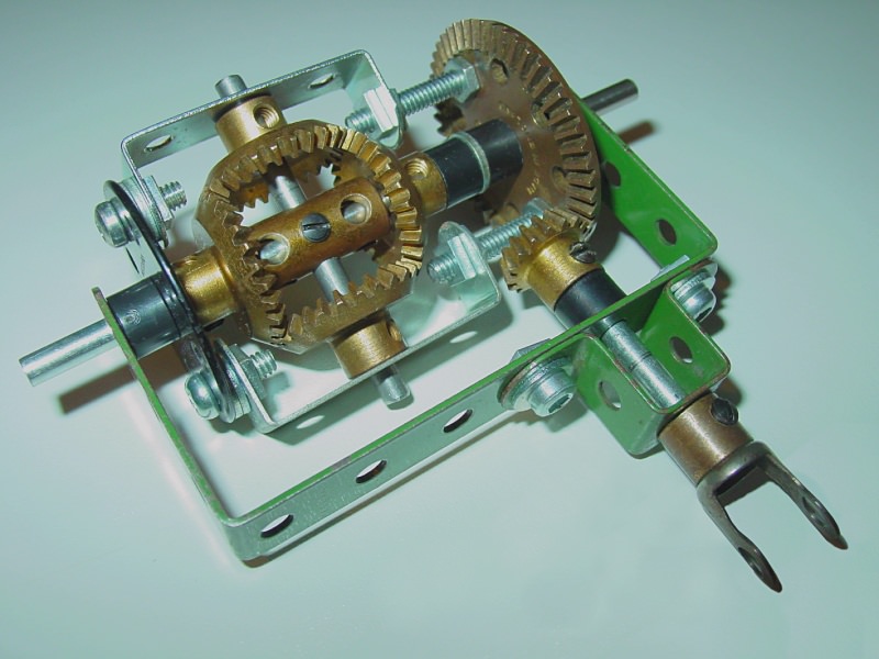
A Meccano differential built using the bevel gears referred to in this article
There have been, and still are, some rogue bevel gears on the market, such as 45° bevels of different sizes that claim to mesh together. They may mesh, but not properly, because their pitch cones do not intersect at the same point (apex) f.
Bevel Gear Proportions, Definitions and Terminology
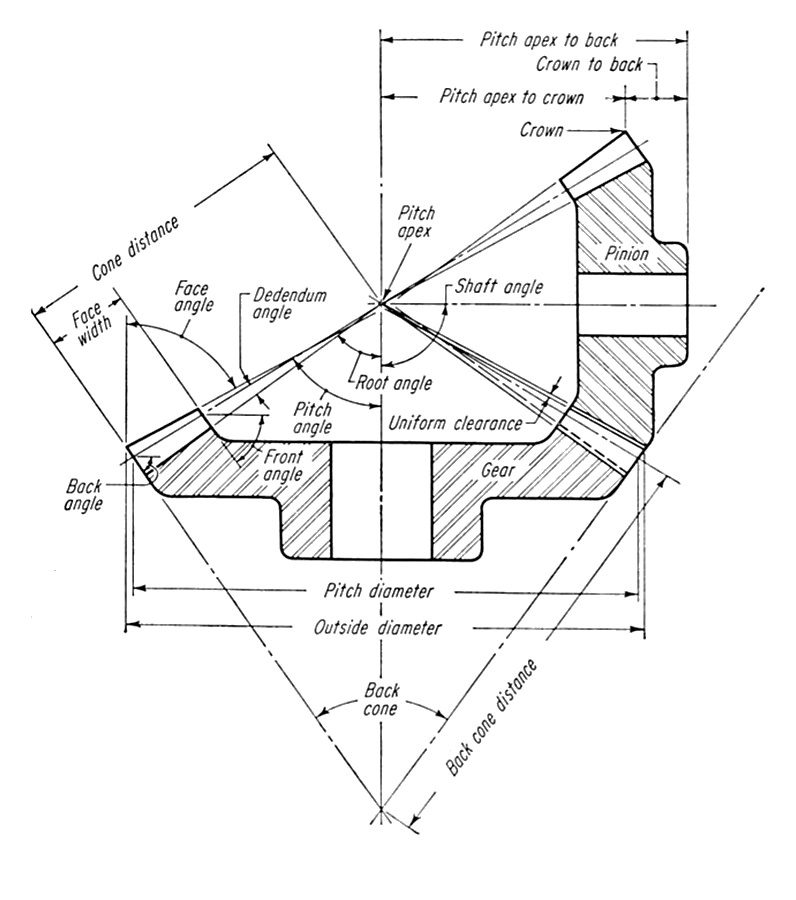
By their nature bevel gears adopt some different terminology to that of spur gears, as defined in figure 1 (reference 1).

Figure 1 Bevel gear definitions
The pitch cones (not defined in figure 1) are the conics derived from the tooth numbers, which lie on the rolling pitch surfaces bounded by the pitch angles. The conical formation at the end of the faces is known as the back cone. These are not essential in the design of bevel gears but may aid setting-up alignment. Also, it is upon the back cones that the pitch diameters are established; their existence may also aid measurement of these features. The inner end of the teeth may also be conical, but again, this is not essential for operation.
The back and inner cones (back and front angles) are often made flat to simplify manufacture and strengthen the gear.
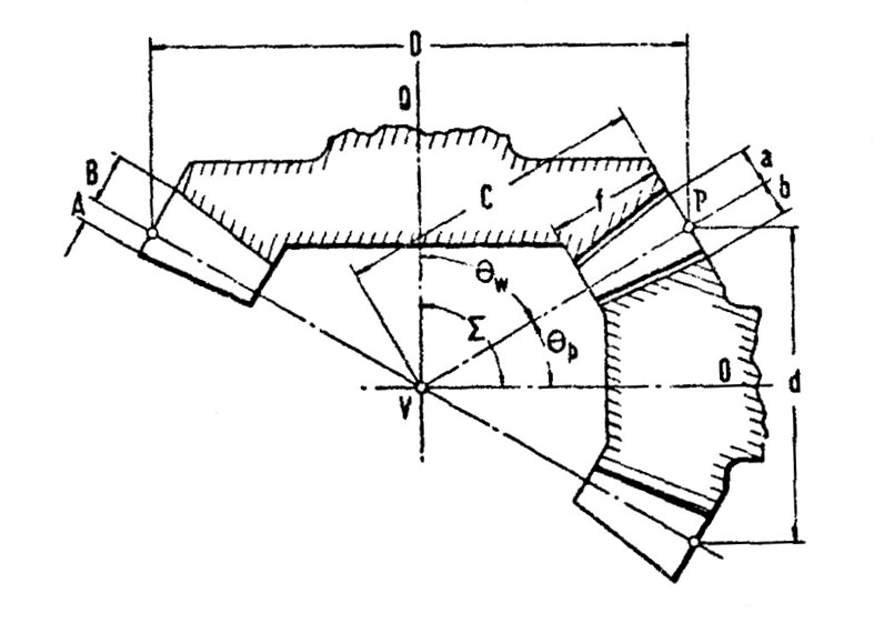
Figure 2 (reference 2) shows the definitions used for calculating bevel gear dimensions and standard tooth proportions.

Figure 2 Bevel gear definitions used for calculating bevel gear dimensions and standard tooth proportions
The calculation sequence is based on known numbers of teeth and pitch diameters.
N = Number of teeth in wheel
n = Number of teeth in pinion
Σ = Angle of gears = 90°
Ratio = N / n
Pressure angle (ψ) = 20°
In the following nomenclature, common abbreviations are shown in curly brackets {}, followed by any mathematical nomenclature applicable in parenthesis (). The equations are numbered in square brackets [] for further reference.
Diametral Pitch {DP} (P)
P = T / D[1a]
or:
P = t / d[1b]
Pinion Pitch Angle (θp)
θp = tan-1(n / N)[2a]
or:
θp = tan-1(d / D)[2b]
Wheel Pitch Angle (θw)
θw = tan-1(N / n)[3a]
or:
θw = tan-1(D / d)[3b]
or:
θw = 90° − θp[3c]
Cone Distance (C)
C = d / 2sin θp[4a]
or:
C = D / 2sin θw[4b]
Clearance (c1)
Standard root clearance value per unit pitch (DP).
Addendum (a or A)
a = A = 1 / P[5]
Dedendum (b or B)
b = B = (1 + c1) / P[6]
Whole Depth of Tooth (h)
h = a + b (A + B)[7]
Nominal Circular Tooth Thickness (g)
g = π / 2P[8]
Tip Diameter (da or Da)
da (Da) = d + 2acos θp (D + 2Acos θw) [9]
Note that there are small differences between the decimal chart values and those quoted on Meccano drawings (reference 3) which are rounded to nearest fractional values.
References
- Dudley, Darle W. Gear Handbook. McGraw-Hill, 1962.
- H. E. Merritt. Gear Engineering. Pitman & Company, London, 1971.
- Blakeborough, Don. Encyclopedia of Meccano Parts.
This article combines elements from articles previously published in 2010 and 2018.
See also parts 1 and 2 of this series covering spur gears and helical gears.