Computer Controlled DSG Transmission
Written by Alan Wenbourne in October 2006
Download this article in PDF format.
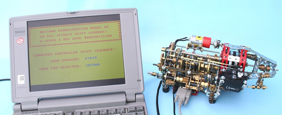
Figure 1 Demonstration model DSG transmission with programmable control
The Volkswagen/Audi DSG Transmission
Early in 2003, Volkswagen introduced a new kind of automatic gearbox as fitted to the Golf RS32. This DCT (Dual Clutch Transmission), known as DSG (Direct Shift Gearbox), was also made available in the Audi 3.2 TT Quattro, who named the DSG ‘S-Tronic’.
Since then, the DSG has become optional equipment on most VW cars and is manufactured in the Kassal transmission plant which is capable of producing 1000 transmissions per day.
The DSG is a kind of automated manual gearbox in that it uses the Borg Warner DualTronic wet-clutch and control system technology in conjunction with a new configuration of VW standard gear and synchromesh mechanisms.
It is a six-speed and reverse arrangement, effectively two gearboxes in one. It uses two clutches, one (C1) serving the odd numbered gear ratios, driving an input shaft to the 1st, 3rd, 5th and reverse synchronizers, and the other (C2) serving the even numbered gear ratios, driving the input shaft to the 2nd, 4th and 6th speed synchronizers. The odd and even geared shafts then drive a common differential gear. Figure 2 is a cut-away of the whole transmission viewed from the front of car. Drive to the rear axle is taken from the output at the left-hand side, to a rear axle-mounted Haldex clutch.
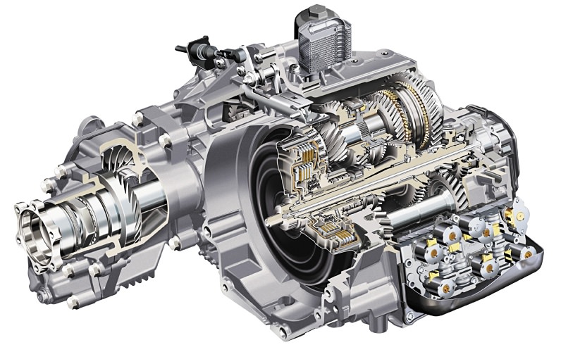
Figure 2 DSG Transmission as fitted to the Audi TT 3.2 V6 Quattro, 4WD version
The principle of operation is that whilst an odd numbered gear ratio is being driven by one clutch (C1), an even numbered gear ratio can be pre-selected, ready for engagement by switching to the second clutch (C2). This action repeats for even to odd gear changes and hence for all upshifts and downshifts.
The result is virtually continuous power flow during gearshifts that are quicker than a manual gearbox and smoother than a conventional automatic transmission. Typical shift times are 0.3 to 0.4 seconds; during upshifts engine power is interrupted for only 8 milliseconds.
Shift quality is ensured by the modulated transfer of torque from clutch to clutch, since in multi-plate wet clutches, better control of friction and wear is possible, and heat energy is dissipated by the circulating cooling fluid. This is unlike dry clutches, which consume their friction material and require eventual replacement.
The DSG arrangement is also more efficient than the conventional hydrodynamic torque converter equipped automatic transmission (a torque converter has a peak efficiency of 86–90% at a pre-determined speed ratio, at all other speed ratios the efficiency falls to zero at stall and run-out).
The DSG in Operation
At launch (accelerating from rest), 1st gear is pre-engaged and clutch (C1) takes-up the drive, then, 2nd gear is pre-selected. At the required shift point, clutch (C2) engages, releasing (C1) and providing a seamless transfer of power from 1st to 2nd gear. At this time 1st gear disengages and 3rd gear pre-selects. At the next required shift point, clutch (C1) re-engages to select 3rd gear as clutch (C2) releases. This sequence continues up to 6th (top) gear, providing that the driver demands continuous acceleration.
All gearshifts are pre-selected and clutches shifted according to a programmed sequence anticipated and controlled by a series of sensors reading ABS wheel speed, throttle demand, vehicle load, acceleration, deceleration etc.
In addition to fully automatic shift programmes for ‘D’ (Drive) and ‘S’ (Sport) performance, the DSG has a Tiptronic function that enables manual shifting via paddles on the steering wheel or sequential up and downshifts via the gear lever +/- function.
Figure 3 shows the overall DSG transmission layout in section and figure 4 the gear and synchronizer layout.
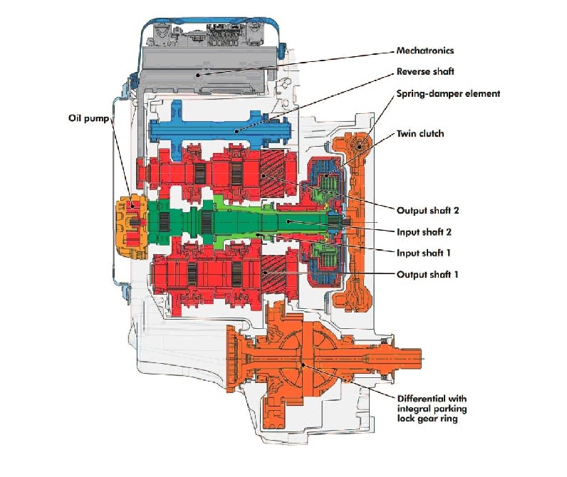
Figure 3 Sectional view of DSG including differential and reverse idler shaft
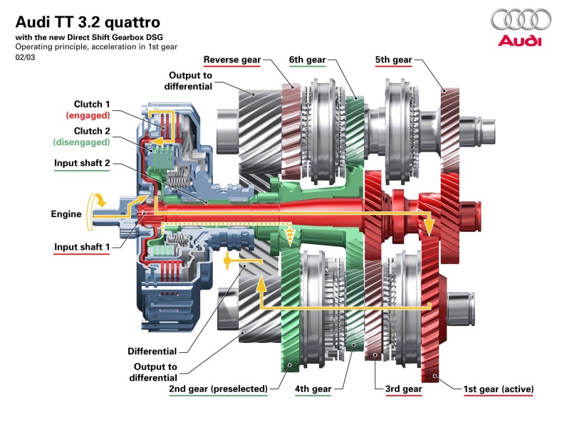
Figure 4 DSG gear/clutch schematic and 1st and 2nd gear drive-paths
History
The beauty and simplicity of the DSG principle is not new, however. The invention of the double clutch gearbox is attributed to a French engineer, Andolphe Kegresse, around 1939 (figure 5). He intended to use it in the Citroen ‘Traction’ vehicle, but business and war circumstances prevented further development.
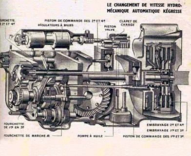
Figure 5 Kegresse dual clutch gearbox proposal
Years later, Automotive Products (AP) proposed a double clutch/gearbox of different design (figure 6). In 1985 Porsche raced a similar gearbox to Kegresse known as PDK (Porsche Dual Klutch), a 5-speed unit with dry plate clutches (figures 7 and 8), whilst Luk/Devotek proposed the PSG (Parallel Shift Gearbox) using wet or dry clutches (figure 9).
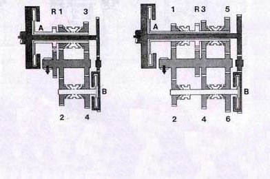
Figure 6 AP schematic for 4 and 6 speed designs
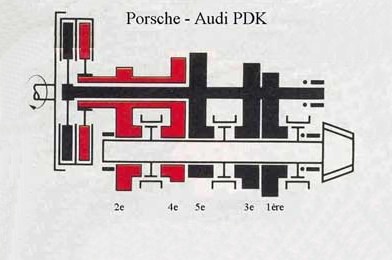
Figure 7 Porche-Audi PDK schematic
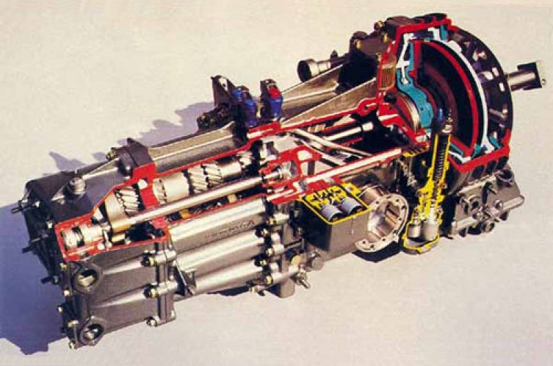
Figure 8 Porsche-Audi PDK
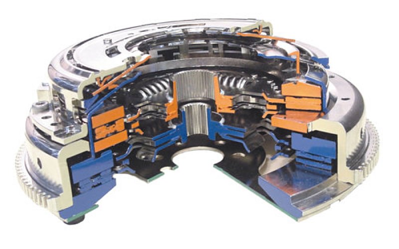
Figure 9 Luk/Devotek PSG twin dry plate clutch
BMW introduced the SMG (Sequential Manual Gearbox) on their M3 model (2002) and Ferrari a similar system on the 575M F1 (Maranello), although these are classed as ‘sport’ transmissions, they are not DCTs but AMTs (Automated Manual Transmissions) using a single dry plate clutch, examples of which are many and varied.
Ricardo UK currently produce the 7-speed DCT used in the Bugatti Veyron.
The advantages of sequential shifting are:
- A quicker shift — the time delay for the gear lever to negotiate an ‘H’ gate is eliminated.
- Shift consistency — no ‘thinking time’ as to which gear is required next, only whether to up or down shift.
- Lever consistency — the gear lever is always in the same place.
- No shift errors or surprises — the wrong gear cannot be selected and the driver does not get ‘lost’ in the shift gate.
- The gear lever occupies less space.
The DSG exhibits all these advantages when in manual mode.
Of the many reviews I have read of cars fitted with DSG, all extolled its advantages and virtues, my favourite paragraphs being from a test drive article of the Audi TT V6 from Car Magazine:
“The best of both worlds advantages of DSG are confirmed by its quick, unambiguous and fail safe operation on the road. Flat-out upshifts are the real eye opener; they happen so fast that you repeatedly catch yourself checking the in-dash display to make sure the gearchange has actually been executed. The pause between shifts you get in a BMW M3 SMG or Ferrari 575M F1 is no longer an issue in the TT V6. Instead, the car storms ahead in one long, unbroken surge, maintaining its momentum all the way from standstill to top speed. The only variation in forward thrust is due to a variation in revs”.
What a testimonial!
The Meccano Model
In planning the model I identified a number of issues and challenges that I considered important to resolve before seriously pursuing the project. These were:
- The size of the model — it would probably be too large for use in any vehicular model of reasonable scale.
- The design of a dual clutch device.
- The type of gear change mechanism (simulating the synchromesh devices of the actual gearbox).
- The method of changing gear — mechanical or electro-mechanical.
- Gear changing strategy — microprocessor or computer control would be the ultimate solution and would better represent the prototype (I have wanted to combine my interest in computers with Meccano for a long time!).
- Because 4WD vehicles with DSG use a sophisticated electro-hydraulic, multi-wet plate, modulated clutch for front/rear speed differentiation (Haldex clutch), a decision on whether to include an inter-axle differential, and where to locate it, was required.
Some initial modelling needed to be done to test the feasibility of the project, and consideration given as to how the issues outlined above might be addressed.
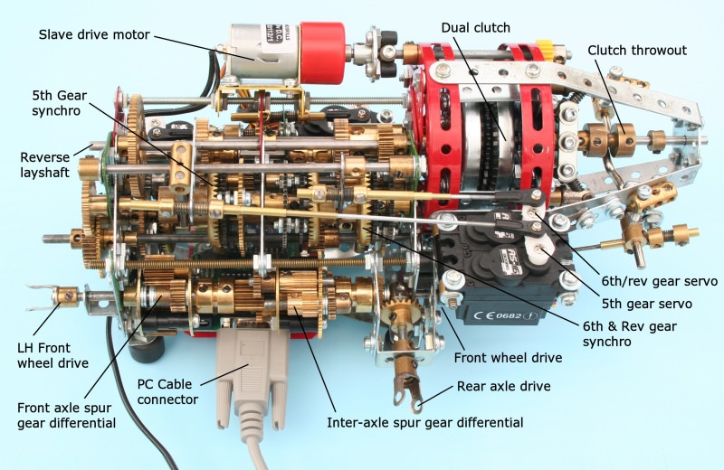
Figure 10 General view of Meccano demonstration model DSG transmission
Watch our video of this model
Model Size
From my DSG data research and a ratio specification provided by VW, I was able to sketch a number of alternative Meccano gear schematic diagrams replicating the original based on one inch centre distance gearing. These diagrams were then optimised to obtain the closest ratio match to the DSG.
As expected, using one inch centres would result in quite a large assembly, but that was necessary to achieve the desired ratio range and gear change method that I had in mind. This potentially classified the model as a “demonstration model” at the outset, as seen in figure 10.
The Dual Clutch
This posed a real problem in that I prefer a clutch design that does not impose thrust loads onto its mounting bearings or structure, when engaged or disengaged, to avoid the resultant frictional drag. This would be particularly desirable in a dual clutch.
A switching device based on an overcentre sprung toggle mechanism took priority of consideration and many variations were modelled and investigated before settling on the final twin sprung link arrangement shown close-up in figures 11 and 12. This design contains the spring force reaction within the unit at all times.
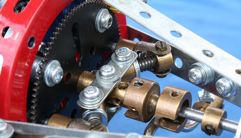
Figure 11 Clutch 1 engaged
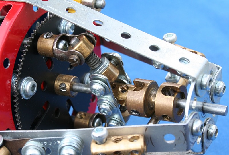
Figure 12 Clutch 2 engaged
The requirement for co-axial output shafts suggested the use of large axle parts to achieve concentric drives in a back-to-back dual clutch arrangement.
A clutch back plate is built-up from a large axle bush wheel and a standard wheel flange, running on a hollow shaft, with a 2” large axle sprocket wheel as the driven plate fixed to the hollow shaft. The sprocket being sandwiched between two 1½” rubber tyres and an additional wheel flange, this forms the basis of clutch 2. Clutch 1 consists of a 1” triple flat pulley without boss but with tyre, mounted on a tri-flat axle, sandwiched between a 2½” faceplate (without boss) as the pressure plate, and a 2½” gear. This assembly is held together with four 1½” double bent strips. The whole assembly is housed within two 3½” circular girders.
Clutch switching is by servo linkage to a crankshaft that engages with a socket coupling, which in turn, snaps the toggle linkage in or out, shuttling the 2½” faceplate to energise either clutch, as shown in figure 13.
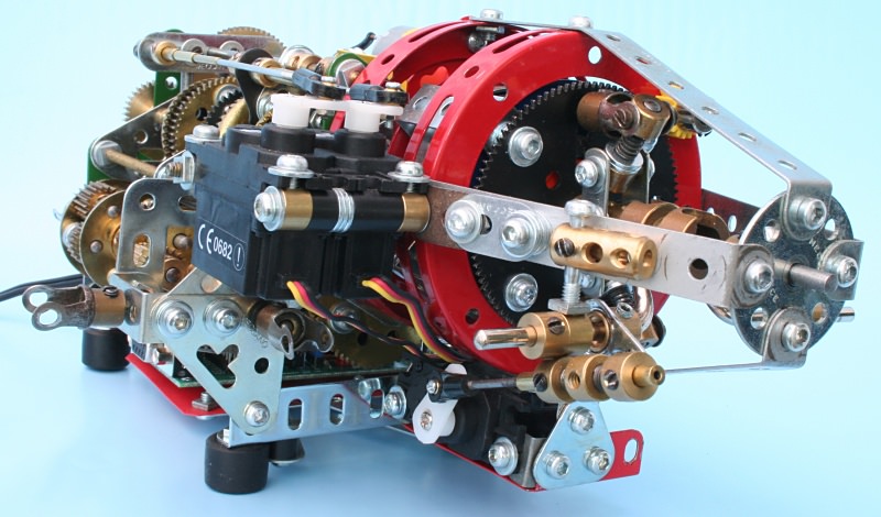
Figure 13 Clutch servo and mounting
Since each clutch output shaft is required to drive two pinions, and it is not possible to mount more than one pinion on to a large axle hollow shaft (clutch 2 output), this created another problem.
It was overcome by arranging the co-axial clutch output shafts offset, but parallel to the split gearbox input shafts, thereby driving the left and right gearbox input shafts via additional pinions from the clutch outputs.
The hollow (clutch 2) shaft is journalled through a large axle square bearing plate on the right hand bulkhead, extending into the gearbox to a large axle coupling with a 28-tooth pinion attached. The tri-flat axle from clutch 1 passes through the hollow axle into the left hand gearbox section, and is also fitted with a 28-tooth pinion. Both 28-tooth pinions drive 25-tooth pinions attached to their respective gearbox input shafts (odd ratios – left side, even ratios – right side). This layout can be seen in figure 14.
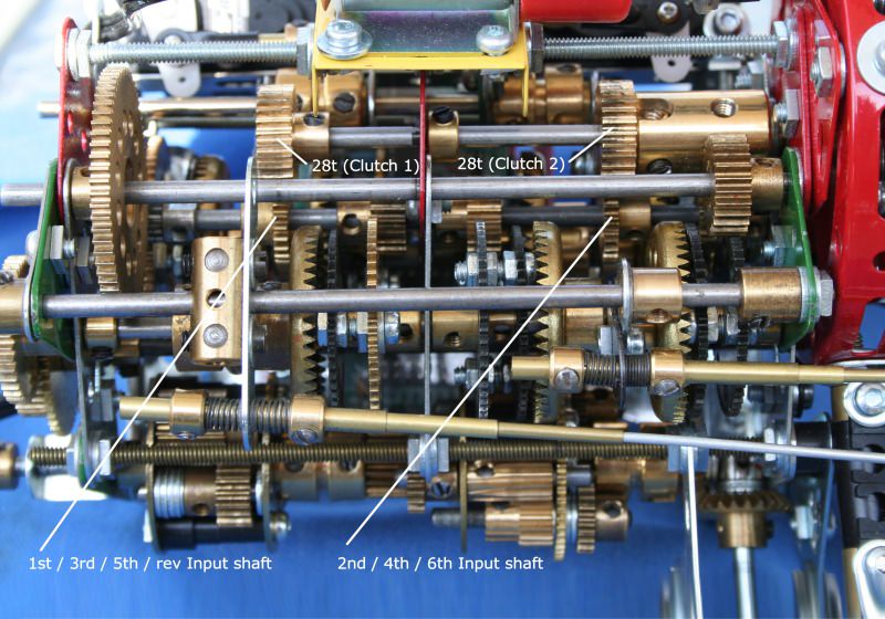
Figure 14 Plan view showing clutch outputs and gearbox inputs
Gear Change/Speed Synchronisation
This needed to be constant mesh, and therefore incorporate some kind of sliding clutch device to simulate the synchromesh action. I did not expect this device to include a friction clutch for speed synchronisation, but was looking for some form of multi-toothed dog clutching feature.
Fixed and sliding bush wheels/discs with engagement pins were tried, but not preferred due to alignment problems, space, and the amount of angular rotation required to achieve engagement.
The availability of 50-tooth discs led to experimentation using these with 50-tooth contrate gears as clutches. This developed into a reasonably compact arrangement that engaged and dis-engaged quite nicely.
Each speed change gear has a 50-tooth disc attached that is free to run on a tri-flat axle, but constrained axially by a small collar between the gear and disc. Two 50-tooth contrate gears attached to each end of a tri-flat socket coupling form the sliding/driving member for gear selection.
Gear Selection and Shift Method
Provisional thoughts of a mechanical shift system with conventional gated gear lever were ruled out as too complex, untidy and unrepresentative of the automatic control of the original. An electric or electronic, radio control or joystick controller, or even better, microprocessor-controlled system was highly desirable.
Trials of electrical means to shift the gears with Elektrikit solenoids proved hopeless through inadequate force capability. A small industrial 12V DC tubular solenoid from Mechetronics proved more effective, but still did not provide sufficient force to consistently shift the gears. Although larger solenoids are available, the fact that solenoids only push or pull, meant that nine sprung return solenoids would be required altogether and the probability of finding a suitable solenoid powerful enough to switch the clutches was doubtful.
I knew that hobby servos, as used in radio control modelling, would have sufficient power, so I experimented with, and successfully shifted the clutches with a servo I had to hand. The next issue was how/where to get a five-channel radio control transmitter/receiver system, even though I was not keen on radio control for the gearbox!
A possible alternative would be the Meccanisms Motorvator™, but enquiries about it revealed that it controls only two solenoids and is relatively expensive.
Microprocessor or computer control was very attractive, since this was the route to automatic control as in the actual DSG. However, this solution was limited by my own knowledge of the technology and programming methods.
Then, through Bryn Jones of Meccanoscene, I learned of Milford Instruments’ servo control boards and software. They produce servo driver boards for driving up to twelve servos, controlled by either on board EPROMS, external BASIC type programmes, or their own software. Now this was looking promising, if I were up to the challenge!
I first purchased Milford Instruments’ software and quickly became familiar with its functionality on my home PC. It can be set-up to command individual servo displacement, direction and speed very easily and can be scripted to perform these commands in the form of a timed programme. Next, I purchased extra servos for the gear changing functions and an eight way servo driver board, applied these to the model and set them up under PC control. The result was very satisfying and performed well, except for the occasional ‘hang’ when a gear would not dis-engage, due to friction between the tri-flat components (more about this later). Figure 15 shows the front mounted servos and servo driver board connections.
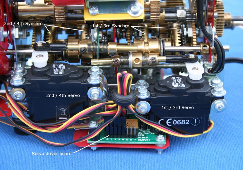
Figure 15 Front view of gearbox
The Milford Instruments literature explained how a program using BASIC code could also be used to control the servo driver board. Since I had had experience using QBASIC some years earlier, a period of revision to update my programming capabilities followed.
A custom QBASIC program would allow more programming flexibility and enabled the on screen display of the gear change events, i.e. which gear was engaged, which gear was to be pre-selected etc.
The resultant program is capable of continuous automatic control, looping through a predetermined and timed shift sequence, or a step-through gear change pattern on command by defined key presses, or up-shift/down-shift gear selection by pressing the plus and minus keys to simulate the manual paddle controls of the actual vehicles.
If this gearbox were in a vehicle, with feedback sensors for throttle position, engine speed and load and road speed, then a completely automatic transmission management programme would be possible, as in the actual vehicle!
Differentials
As the basic transmission is a transversely mounted front wheel drive configuration, I decided to use a spur gear differential in the front axle for compactness and ease of driving from the parallel gearbox output shaft.
I considered the option of incorporating a mechanical inter-axle differential in lieu of the Haldex coupling used in the original vehicles. Space appeared to be available, so the concept of taking the gearbox output drive to another spur gear differential developed, and resulted in the parallel inter-axle/front axle differentials seen in the model.
Other Constructional Detail
The frame consists of left, centre and right bulkheads made-up from triangular and other plates, tied together by four screwed rods and one axle rod. The left and right bulkheads are extended downwards to angle girders, to which rubber tyre feet are attached. Diagonal strips underneath support the servo driver circuit board, whose components are protected from above by a clear plastic plate.
The front lower portion carries a strip to which the 1st/3rd and 2nd/4th servos are attached. The clutch servo is mounted on a flanged plate underneath the clutch housing and also tied to the clutch cage extension supporting the input shaft, as shown in figure 13.
Meccano parts did not allow direct gearing of the synchroniser shafts to the differential, so an additional (to the original DSG) intermediate output shaft was added to relay the synchroniser shaft drives to the inter-axle differential, indicated in figure 16. The gearing for this is outside the left hand bulkhead and has the added advantage of allowing better optimisation of the overall gear ratios compared to the original.
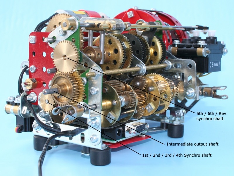
Figure 16 Left-hand side/rear view showing output relay gearing
The standard Ø1.5 servo control rod size was built up to Ø4.0 with concentric brass tubing, with each tube interface secured with anaerobic adhesive. The control rods are spring centred to the shift forks so as to avoid any damaging servo over-travel in setting-up.
The problem of the gear ‘hang’ mentioned earlier was due to the frictional resistance against sliding between the tri-flat socket couplings and their shafts. Polishing and applying low friction compounds to the sliding surfaces improved this condition.
See more photos of this model.
Gear Ratios
Much has been written on the subject of automotive gear ratios needing to follow arithmetic or geometric progressions. However, for high-speed vehicles, the ratio steps need to be more closely spaced towards the higher speed gear ratios. This is because aerodynamic drag increases in proportion to the square of velocity and hence power is a cubic function of velocity. Therefore, rather than each up-shift being made at similar engine speeds, subsequent up-shifts are executed at progressively higher points on the engine’s power curve. I was not able to match the DSG ratio steps all the way through the range, but consider the trend achieved as acceptable.
| Gear |
Meccano Model |
|
VW DSG |
| |
Ratio |
Step |
Ratio |
Step |
| 1st |
66/11 x 50/25 |
= |
12:1 |
|
14.052:1 |
|
| |
|
|
|
1.50 |
|
1.692 |
| 2nd |
60/15 x 50/25 |
= |
8:1 |
|
8.305:1 |
|
| |
|
|
|
1.33 |
|
1.409 |
| 3rd |
57/19 x 50/25 |
= |
6:1 |
|
5.894:1 |
|
| |
|
|
|
1.50 |
|
1.346 |
| 4th |
50/25 x 50/25 |
= |
4:1 |
|
4.379:1 |
|
| |
|
|
|
1.33 |
|
1.253 |
| 5th |
57/19 x 38/38 |
= |
3:1 |
|
3.494:1 |
|
| |
|
|
|
1.20 |
|
1.21 |
| 6th |
55/22 x 38/38 |
= |
2.5:1 |
|
2.888:1 |
|
| Reverse |
66/11 x 50/25 x 38/38 |
= |
12:1 |
|
12.509:1 |
|
Figure 17, the Meccano model gear schematic, shows the clutch arrangement, gearing layout, and differential configurations diagrammatically.
Figure 17 Meccano model gear schematic
References
- Jost, K. — July 2003, A Different Automatic, Automotive Engineering International, vol. 111, № 7, p. 32–36
- Audi UK — Glossary — Direct Shift Gearbox (DSG)
- Wikipedia — Twin-Clutch Gearbox
- Vondruska, J. — February 2003, First Drive: Audi TT DSG
- RSportsCars — Ferrari 575 Maranello F1
- Harris, B. — How Dual-Clutch Transmissions Work
- Raul, P. — The Revolutionary VW-Audi Double Clutch Transmission
- Milford Instruments Limited
This article © 2006 Alan Wenbourne.