Mini Stiff-Leg Derrick
Written by Chris Warrell for our June 2004 Newsletter
Several meetings ago the Secretary’s Challenge was to construct a micro model, the definition being that the parts, when loose, will fit into the palm of one hand. There is a certain amount of leeway here depending upon how you define the palm and, of course, how big your hands are!
Stiff-Leg Derrick
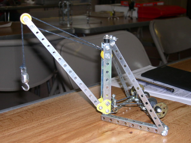
My model is based on the 1930s Super Model № 6, but is one quarter the scale. The base is triangular in plan, and is formed of a 4½” narrow angle for the two short sides and two 4½” narrow strips overlapped by 6 holes to give a 6” length for the back edge. This is strengthened by two 2½” narrow angles. All three sides are connected through their end holes. (Anyone who hasn’t forgotten their Pythagoras will realise that this doesn’t give you a right angle triangle, but it’s so close that it’s not worth worrying about.) On the rear member is the winding mechanisms for luffing and raising the hook. Each of these consists of a 2” rod with, at one end, a built up crank from a 1” bush wheel and a plastic spacer loose on a bolt. The rod is supported on a pair of narrow 1” x ½” angle brackets. A vertical pivot bolt on a narrow Z bracket (my new name for the reversed angle bracket) guides the cord.
The ‘king post’ (if that is the correct term) is a pair of 4½” strips, joined at the bottom by two 1” triangular plates and a 1” x ½” double angle bracket (with a fishplate in the bottom of the latter, so that the vertical bolt will go through the bracket and the round hole of the fishplate, such that the slotted hole will stick out towards the back to take the cord guides), and at the top by a ½” x ½” double angle bracket. Through the second hole from each end is a pair of ½” plastic pulleys. The king post is bolted at the bottom through the corner hole of the base, but loose so that it can swivel. At the top it is bolted through the centre hole of a 1” corner bracket. Two 6½” narrow strips, to form the ties, are bolted, one each side, to the aforementioned corner bracket via a narrow angle bracket at the top, and to the end hole of the base. This should give you the distinctive triangular shape — if it’s any other shape, you’ve gone horribly wrong!
The jib is a pair of 7½” narrow strips, pivoted on the remaining hole of the triangular plates, and bolted together one hole from the top, but spaced apart to allow for a ½” plastic pulley to be journalled on a bolt in the last hole.
The cord guides consist of a coupling with a 11/8” bolt through the centre hole fixed to the fishplate, and a pivot bolt screwed into the remaining two holes, so that you have three vertical pins. I managed to get a square nut at the bottom of each one to just line up. The centre bolt head is above the others so that you can easily feed the cord through, which is all that remains to do.