Pegasus Rolling Lift Bascule Bridge
Written by Alan Wenbourne in February 2022
Background
The Pegasus Bridge spans part of the Caen Canal in Normandy, France. It was built in 1934 and was the subject of an operation by the British 6th Airborne Division in 1944, led by Major John Howard, to capture, defend and hold it against attack until relieved by D-Day invasion forces. The 6th were despatched in three Horsa gliders and landed less than 50 meters away from the bridge (figure 1).
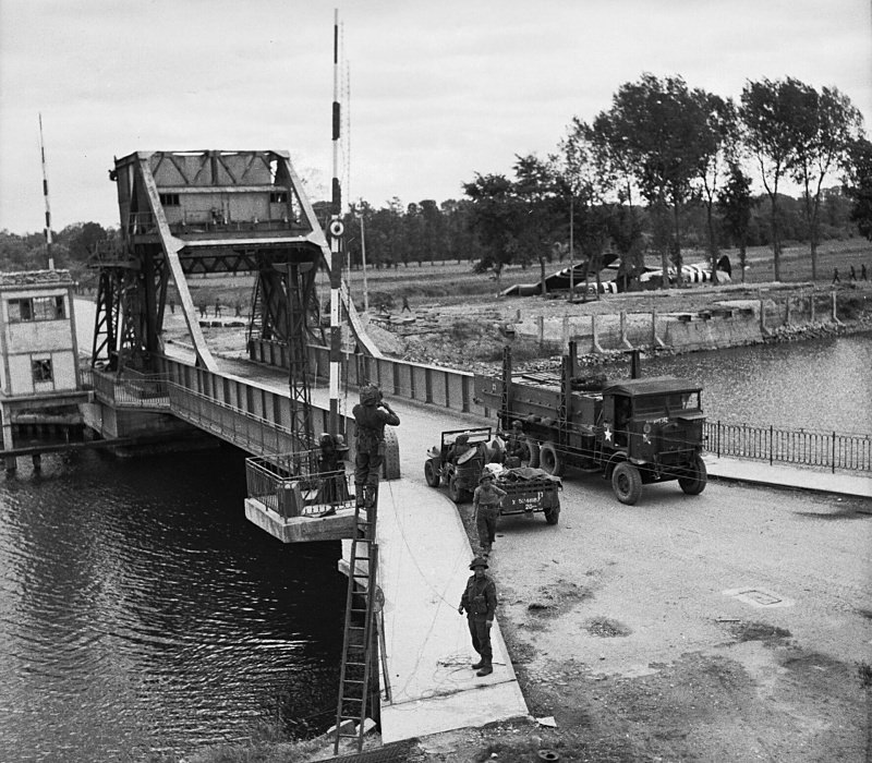
Figure 1 The captured Pegasus Bridge in 1944, with the gliders in the background
The bridge was originally named Bénouville after the nearby village. Due to its successful capture it was renamed Pegasus Bridge in honour of the operation and the emblem of the flying horse worn by the British airborne forces.
In 1994 (50th anniversary) the Pegasus Bridge structure was replaced by a new slightly larger design (figures 2 and 3), and the earlier version was moved to a nearby site, becoming part of the Memorial Pegasus Museum.
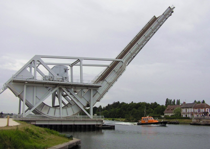
Figure 2 The 1994 replacement Pegasus Bridge in the raised position
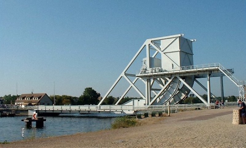
Figure 3 The 1994 replacement Pegasus Bridge in the lowered position
The bridges are of a particular sub-group of rolling bridge known as ‘Scherzer’ rolling lift bascule bridges. William Scherzer (1858–1893) was an American bridge designer/builder who, during his short lifespan, made significant contributions to bridge design and construction.
The Scherzer patented principle is to roll the structure on a curved treadplate, causing its axis of roll, and hence the structure, to retract from the pier/waters edge, thereby maximising clearance for vessels to pass.
It is interesting to note the advantages of the Scherzer type rolling lift bridge over other methods for spanning waterways (reference 1):
- Less expensive than high level or swing bridges or tunnels.
- No mid-channel obstruction.
- Occupies much less space than swing bridges.
- Does not require deep excavation(s) — as required by bascule counterweights.
- Minimal bearing friction.
- No fixed trunnion.
- Horizontal waterway clearance increases with lift.
- No waterway obstruction during construction.
- Can be double-decked.
A 1913 Scherzer Rolling Lift Bridge Company promotional advertisement (see figure 4 and reference 2) describes the advantages and function in more detail.
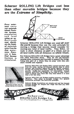
Figure 4 Scherzer advertisement
Initial Observations
I came across images of the Pegasus Bridge whilst browsing the Internet. Previous thinking led me to believe that rolling lift bridges were fairly simple structures, but the more I looked at this one, the more I became interested in its apparent complexity and how it works.
Despite the plethora of pictures of these bridges available, part of the operating principle remains a mystery to me. The 1934 bridge (according to reference 3) has a large gearwheel and pinions on the axis of roll meshing with racks on both sides. This mechanism translates the roll axis horizontally, thereby providing the raise and lower function. I suspect the 1994 version operates similarly but uses hydraulic motors to drive the axis of roll.
Both structures have a ‘garden shed’ like hut, which travels with, but remains level during the roll axis translation. The shed is obviously the machinery cabin, but exactly how it is stabilised to remain level and transfer drive to the rack pinion is not clear, so I applied my own interpretation of the system that hopefully replicates the real thing.
The magnitude of the counterweight, and the fact that the centres of gravity of the counterweight and bascule vary in distance from the roll axis in operation, make interesting study.
The Model
The bascule design obviously needed to be very robust to carry the masses involved, although the usual problem of increasing size would demand greater structural strength. I initially based the bascule length on 25½” angle girders, and then thought about the curved treadplate requirements. A 17 x 2 hole, 5¾” outside radius curved flat girder (quadrant) with additional inner and outer curved strips formed the basis of the treadplate, giving a 6¼” roll radius. Scaling photographs then indicated that the bascule needed to be 28” long, so it was extended accordingly, setting the scale at about 1:45.
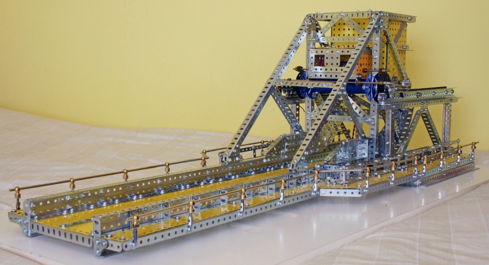
Figure 5 The model in the lowered position
I decided at an early stage to use a 16DP rack and pinion system with 8-tooth pinions to take advantage of their greater depth of tooth, as this would provide some tolerance in roll radii variation.
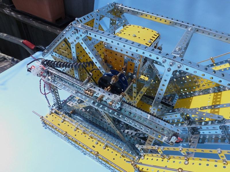
Figure 6 The rack and pinion system
The entire load is taken between the treadplate and its track, none by the rack and pinion drive, and the treadplate to track interface should have some kind of toothed arrangement to avoid slippage. This was achieved by rolling a 19-hole flat girder to form the treadplate, the slots of which engage pivot pins protruding through the holes of a 1 x 3 x 1-hole channel section girder forming the tracks each side.
The rest of the supporting structure, bascule and counterweight housing were constructed as close to scale as parts allowed. Angle girders are ‘boxed’ to simulate the ‘I’ beams of the original structure.
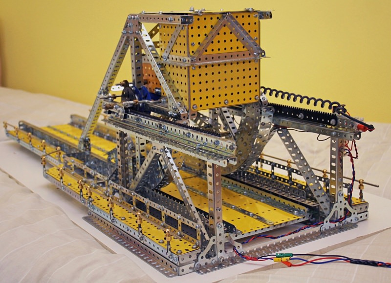
Figure 7 The treadplate and its track
As the roll axis is not load bearing, I assumed that a standard axle rod would suffice to provide the horizontal drive force. As the original structure exhibits a large tubular hub, the model uses a long cylinder with 2½” faceplate end caps.
Once the main structural members were made, it was time to experiment with counterweight ballast. (The actual bridge uses 106 tonnes of concrete!) Initially bags of nuts and bolts were used, as I had no idea of how much weight would be required. With the counterweight box overflowing, the bascule rolled very smoothly and interestingly — when balanced halfway, it was biased to overbalance when raised and under balance when lowered. I like to think this is a feature of the original design intent reflected in my model. This indicates that the centre of gravity of the bascule mass passes either side of a vertical through the axis of roll in mid position.
The walkways were added to the bascule and main structure, which then required additional ballast!
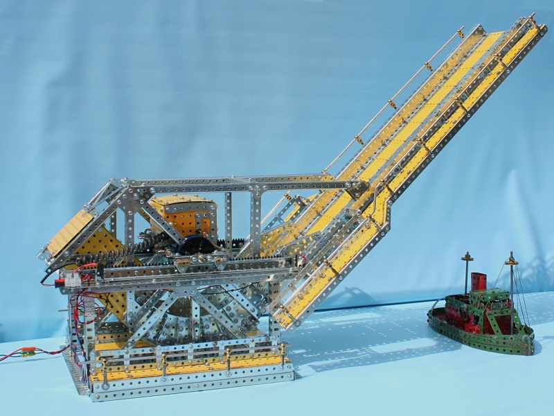
Figure 8 A side view of the model
The next phase was to design a drive based on the 1934 original, meaning that the model would become a hybrid of both original bridge versions. The 16DP rack strips were positioned on channel sections of girders using their slots and shims to give a running clearance to the drive pinions. Rolling the bascule manually confirmed smooth running of the pinions to the racks.
A mockup machinery cabin was attached to bogie-like members by transverse axle rods. These bogies pivot on the pinion rod and have upper and lower rollers engaging the top flange of the channel girders, the object being to provide vertical guidance and prevent any tendency for the pinions to jump teeth. These bogies also provide a means of maintaining the machinery cabin in level attitude during horizontal displacement. The pinion rod also carries 2½” gears either side. A drive axle rod passes through the machinery cabin with 19-tooth pinions at either end that engage with the 2½” gears. A motor in the machinery cabin provides the power to roll.
This arrangement works very smoothly and quietly without any indication of strain. The three transverse axle rods are arranged not to obstruct any part of the bascule structure during the rolling action. I made the rearmost transverse axle rods crankshafts, thereby allowing the bascule structure additional angular lift to 82.5°.
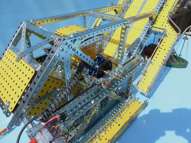
Figure 9 The machinery cabin
The motor is a Como Drills 4.5V–15V planetary gear motor of 27:1 reduction. Operating it at 5.5V seems to be optimal, and it takes 25 seconds to raise or lower the bascule.
For transportation it is necessary to separate the bascule from the fixed frame and I wanted the counterweight to be removable also. After some time trying to find suitable (strong) boxes to load with nuts and bolts that would fit into the housing, I gave in and constructed a separate box using old flanged plates that closely fitted the counterweight housing. Having established that solid steel weighs about twice that of nuts and bolts for a given volume, the box was lined with 2” square x 1/8” thick flat steel plate washers and then filled with nuts and bolts. The removable counterweight weighs in at 12lbs (5.5kg).
An electrical circuit was devised using micro-switches to limit the raise and lower travel. A double pole double throw switch provides control of the raise and lower functions.
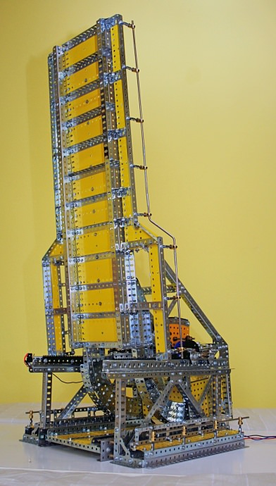
Figure 10 The model in the raised position
Showing the model at club meetings prompted several lively discussions as to the position of the centre of gravity (mass) of the bascule, two suggestions being “at the centre of roll” and “vertically above the point of contact with the track at all times”. For these conditions to be true the centre of mass would have to be at the centre of roll. If this were the case, a considerable amount of otherwise unnecessary counterbalance mass would need to be concentrated above the centre of roll.
My study (figure 11) proposes that the centre of gravity is somewhere within the sector of roll, and below but close to the centre of roll, where it produces a small moment about the vertical roll axis at the fully raised and lowered bascule positions. This is confirmed by the fact that the bascule balance is biased in the lowered and raised position — a design intent that had not escaped the attention of William Scherzer.
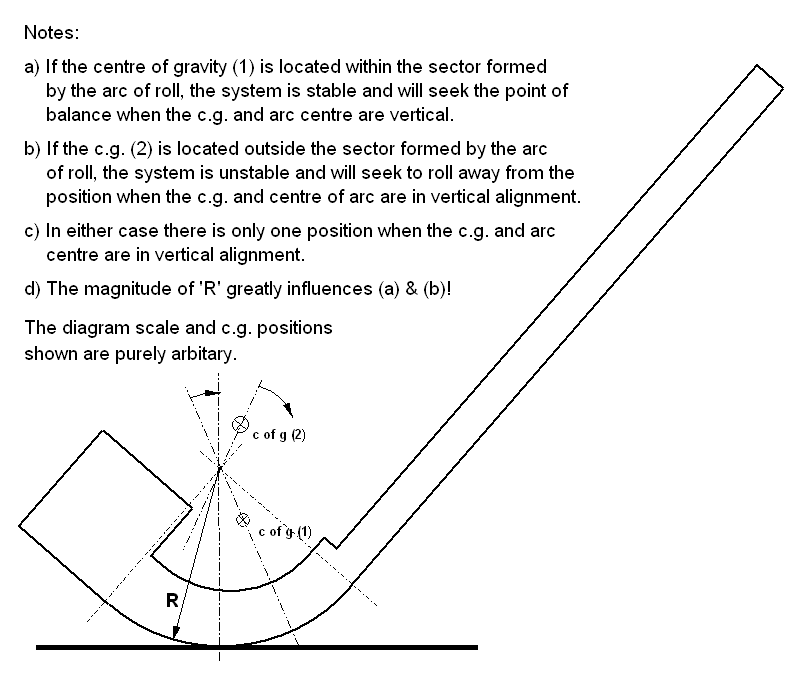
Figure 11 Centre of gravity study
During construction of the model I became aware of the significance of the Pegasus Bridge as it featured in TV programs and publications in the lead up to the 70th anniversary of D-Day (6th June 1944) during May and June 2014. So, by sheer coincidence, I was able to show my model at the 7th June meeting of the Runnymede Meccano Guild, one day after the 70th anniversary!
References
- Williams, Archibald. Engineering Wonders of the World, Volume II. Nelson, 1910.
- Cassidy, Lisa. “Scherzer rolling lift bridges, North Wall Quay and Custom House Quay, Dublin 1.” Built Dublin, 2013, www.builtdublin.com/scherzer-rolling-lift-bridges-north-wall-quay-and-custom-house-quay-dublin-1. Accessed 8 February 2022.
- Taylor, Dan. “Pegasus Bridge.” Dan Taylor Modelworks. www.dantaylormodelworks.com/pegasus-bridge-8-p.asp. Accessed 8 February 2022.