Oshkosh M1070/M1000 Heavy Equipment Transporter System
Written by Alan Wenbourne in July 2025
Origin
At the Welling 2023 Model Show and Open Day I saw miniature plastic models of this vehicle and system which attracted me to the idea of modelling it in Meccano.
Initial Considerations
As usual, my first thoughts were about determining the size and scale of the model, probably based on wheel size.
My desire was for realistic wheels and tyres, so I reviewed what is available in the Radio Control (R/C) model market. There is a vast choice here where compatibility, adaptability with Meccano and weight carrying capacity can be challenging.
I came across a tyre and wheel (reference 1) which had the exact tread pattern of the prototype tractor, 4½” diameter by 1½” wide, so I ordered a set of four. These proved to be of excellent quality, the tyre being very supple with a sponge rubber inner. The hubs are a beautifully engineered three piece design that trap the tyre beads forming an air-tight seal, none of which could be used due to their metrics not being compatible with Meccano parts.
After a little experimentation, fitting them onto black 2” pulleys (which have a wider vee-groove than others) with wheel flange naves seemed to be satisfactory, subject to load carrying capacity, but since the vehicle is an eight-wheeler I believed that they might be OK.
The size of these tyres indicated a model scale of 1:12, resulting in a combined tractor and trailer overall length of some six feet!
Other Design Challenges
Before proceeding with any vehicle, architectural or structural modelling, the trailer wheels and bogies were identified as an important design consideration. Apart from deciding on a suitable wheel/tyre, these have to satisfy five important functional requirements — wheel rotation, bogie oscillation (camber), steering, suspension and retraction to aid loading.
To scale, the trailer wheels needed to be 2.55” diameter. The 142H/D tyre suited this perfectly, but I had only two and finding more proved impossible. So, although undersize, I opted for the 142 standard version on 1½” pulleys. After several iterations, a suitable bogie satisfying the five required attributes with dual wheels developed. A mock-up deck with a pair of bogies demonstrated the arrangement (figure 1).
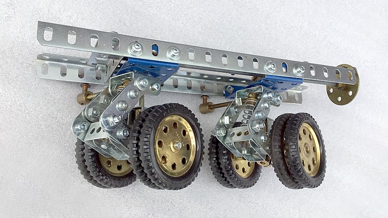
Figure 1 Bogies
During the model’s development a chart was compiled to document the prototype vehicle’s statistics and calculate the respective model proportions, dimensions and scale (appendix 1).
The Tractor
Chassis
A 3D computer model of the tractor and trailer (reference 2) proved invaluable in analysing the scale and details of the prototype for modelling purposes.
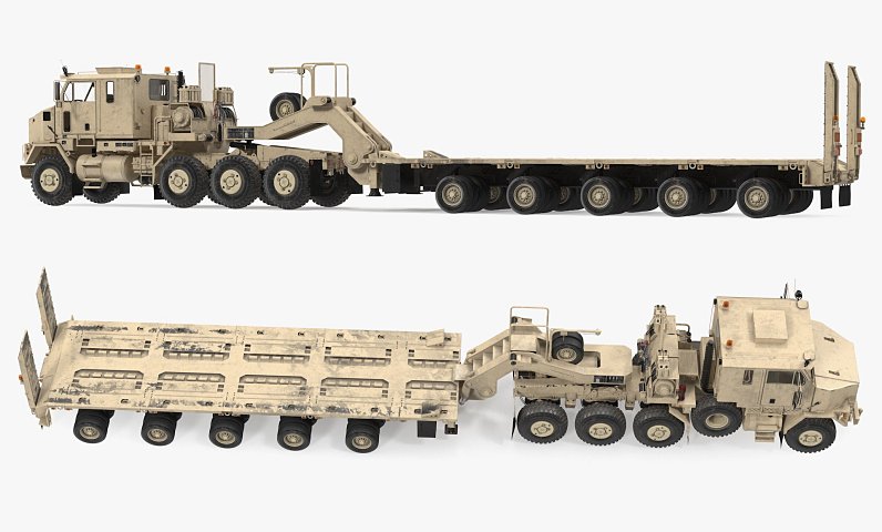
3D images of the tractor and semi-trailer
A 30” x 3½” x 1” angle girder frame forms the chassis. Rigid and steer drive axles were modelled with contrate gear differentials, with the three rear axles mounted on replicated Hendrickson-Turner Air Ride suspension frames, and spring modules formed with 1” bush wheels and compression springs simulating the bellows.
The very soft and pliable tyres were mounted on 2” pulleys as a temporary measure in the knowledge that the model’s weight would eventually be too much for them. This enabled the chassis to be mounted on wheels.
A three forward and reverse, sliding layshaft gearbox, based on my design (reference 3), was fitted with a two speed range change auxiliary box, giving 6F–2R gears.
A survey of available geared motors which could provide a model velocity of around walking pace was unfruitful, so a Meccparts 900rpm geared motor was fitted, if only to run some off-load testing of the initial running chassis (figure 2).
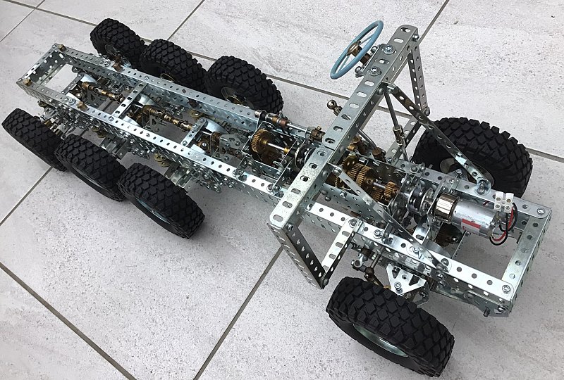
Figure 2 Initial running chassis
Due to the fore and aft stroke of the sliding layshaft, a lot of time was wasted trying to shorten the driveline arrangement in order to make space for a clutch, which would allow fitting a larger motor and primary reduction gearing.
Alternative Transmission
A survey of past Meccano gearbox designs did not reveal anything suitable, so a new 3-speed and reverse design based on sliding gears was constructed, incorporating a two-speed range change, giving six forward and two reverse gears. This created enough space for a clutch (reference 3) and a radio control truck motor (reference 4).
Now, the rolling chassis weighing in at 8kg with battery (mounted inside the fuel tank) is too heavy for the squidgy tyres, producing much resistance to rolling motion! Time was spent considering tyre inserts to increase stiffness/reduce compliance. Doughnuts cut from heavy-duty upholstery foam were tried but were found not to be stiff enough. Various methods of inserting wooden segments were abandoned. Then ‘other’ Meccano circular parts were considered — the 3” pulley with tyre at 4” outside diameter would be perfect, if it could be fitted into the R/C tyres. Fortunately, the compliance of the tyre rubber allowed this to positive effect on all eight units, reducing the rolling resistance considerably, from 8kg to 0.5kg (1/16th!). (My luggage weighing scale proved handy for measuring the rolling resistance!)
With new electronic speed control (reference 5), radio transmitter (reference 6), steering servo (reference 7) and battery (reference 8), the chassis runs well in 1st gear but is plagued with slipping grub screws!
Figure 3–6 show the front bulkhead and various chassis fittings including the replacement gearboxes, clutch, motor, radio control receiver, electronic speed controller, fuel tanks either side and final drive arrangement.
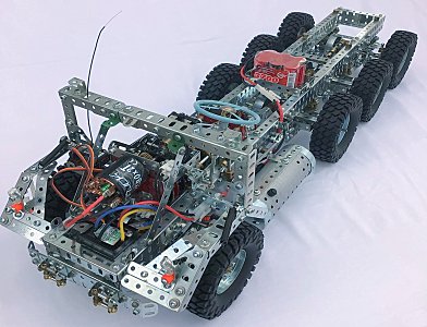
Figure 3 Front bulkhead
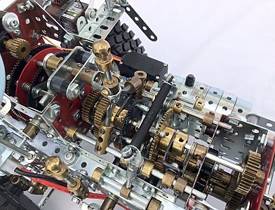
Figure 4 Gearbox and clutch
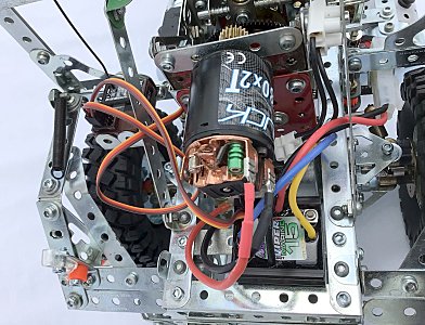
Figure 5 Motor
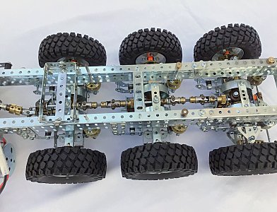
Figure 6 Final drive arrangement
The tilting opening bonnet and cab with opening doors were then modelled.
The Fifth Wheel
I knew nothing about fifth wheels or how they worked, so the subject was studied only to realise the challenge of producing one in Meccano. I recalled seeing something about them in an issue of Constructor Quarterly some years ago. A search revealed Bill Charleston’s article in issue 52 (June 2001). This was constructed and it worked perfectly. I made some changes in order to adapt it to my vehicle and made a tilt plate from a 5½” x 3½” flat plate. As far as I know these were never produced in zinc finish, so I removed the paint from an old red one, cleaned-up the surfaces and cut to shape. A tilting feature and guide ramp were modelled, near to scale of the prototype (figure 7) showing king pin locking control.
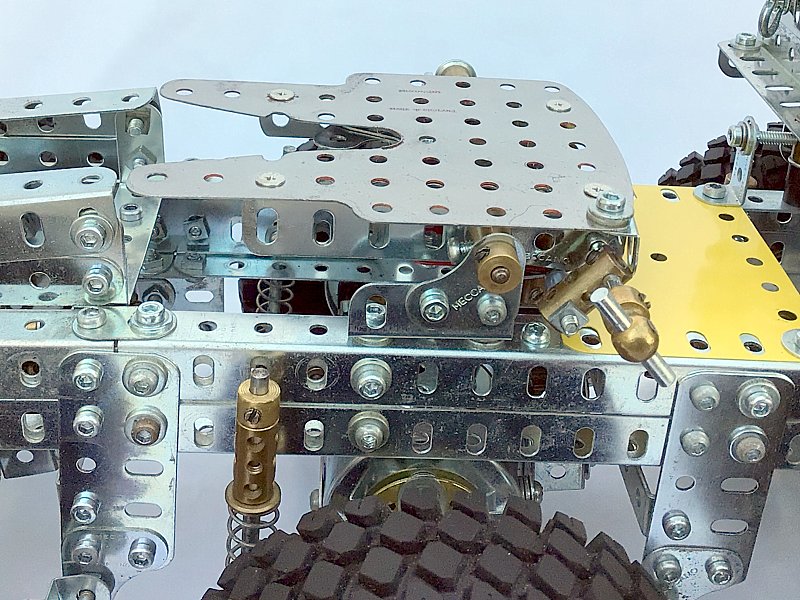
Figure 7 The fifth wheel
Winches
The M1070 is equipped with twin winches to assist loading. These sit over the second axle. A Meccparts 15rpm geared motor drives a layshaft carrying two disconnectable drives, one to each winch drum. Power is self-contained through a 6V DC rechargeable battery (reference 9) via a double pole, double throw (DPDT) switch to the motor. The drives are selected by levers atop the winch housing (figure 8).
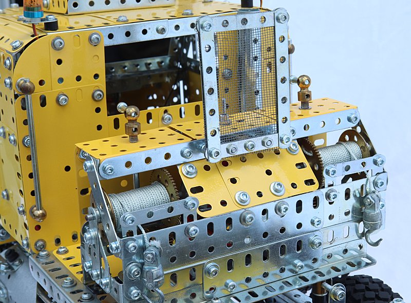
Figure 8 Dual winches and controls
Suspension Re-evaluation
It was obvious from initial trials that a complete re-evaluation of the suspension system was necessary to maintain traction under even slightly undulating terrain. The spring modules were too stiff and the replica suspension did not allow for axle oscillation, so any depressions in the terrain induced loss of traction through insufficient jounce.
A complete re-think of the suspension arrangement resulted in a more compliant system based on larger compression springs (120h). Additional transverse freedom was achieved by mounting the suspension arms outside the frame, also allowing axle oscillation (figure 9).
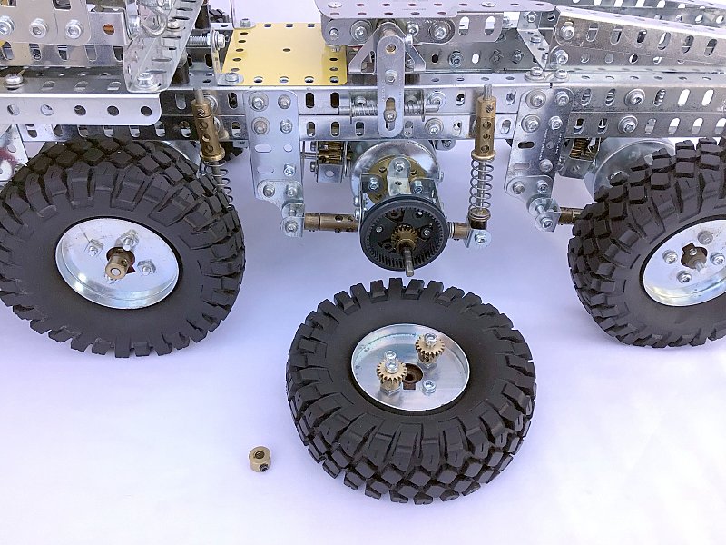
Figure 9 Revised bogie suspension and reduction hub gearing, also showing suspension detail
Drivetrain Re-assessment
Initially I shied from considering the complexity of planetary reduction hubs, but maintaining the tightness of the many grub screws in the drivetrain was proving to be a problem.
Hub reductions would reduce the drivetrain torque by several orders of magnitude and overcome the problem, so it had to be considered.
A compact hub reduction based on the 2½” gear ring was designed and built into the front steer-drive axle. The problem was that I had only three gear rings and needed eight! I then discovered how rare these parts are! My dealer came to the rescue with one gear ring, which enabled the building of two more hub reductions for the rear steer-drive axle.
An alternative to gear rings could be to use the plastic wheel 187c (A187) which has 57 internal teeth but is much too long to accommodate in the steer-drive axles, but if it were shortened, may be a suitable for the rigid axles. Having successfully cut four to 10mm long, they were built into planetary hubs for the rigid axles. They cannot be secured so are allowed to float on bolt thread ends.
Both the gear ring (180a) and wheel hub (187c) exhibit the same bad design, in that the internal teeth are cut/moulded to standard proportions, instead of being engineered properly with allowance for tooth clearance, manufacturing tolerances and backlash. This makes it difficult to design a free running planetary gear set using 19-tooth sun and planet gears. It can be eased by mounting the planet gears on screwed components in order to allow extra radial freedom, and by positioning of the planet axes closer to the sun gear axis. It is also better to use Binns Road narrow face pinions because the aftermarket modified versions may have burrs at the tooth ends. I opted to use two planet pinions rather than three to minimise tightness (figure 9). Also, made sure not to use the older 20-tooth pinions!
Rear Steer-Drive Axle
This axle and suspension had to be completely re-designed in order to incorporate planetary hub reduction gearing. In the new version the steering knuckles provide excellent steering lock.
The axle support also includes a leading longitudinal journal ahead of the axle that allows effective oscillation, and the suspension struts relocated inside the chassis frame members allow good steering lock (figure 10).
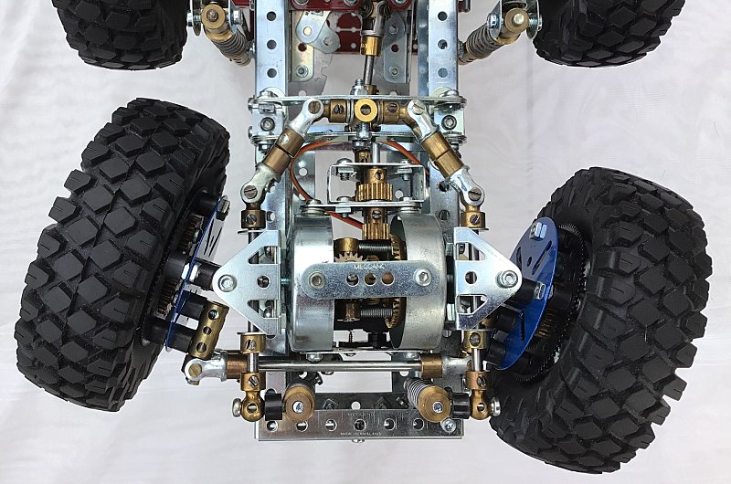
Figure 10 New rear steer-drive axle and suspension
The steering function of this axle needs to be synchronised with the front steering axle. Mechanical connection proved difficult to devise, so an additional servo was fitted for testing. Of course it steered the wrong way! Switching the polarity of this servo did not work and repositioning the servo has so far proved impossible — work in progress!
Bodywork
The bonnet (engine hood) is hinged at the lower front edge and held closed with spring straps either side.
To enable easy access to the chassis and driveline for servicing, the cab and winches were combined as one module and attached to the frame and dashboard by only six bolts.
An NiMH rechargeable battery (reference 9) is positioned in a box at the rear of the cab for powering the winches.
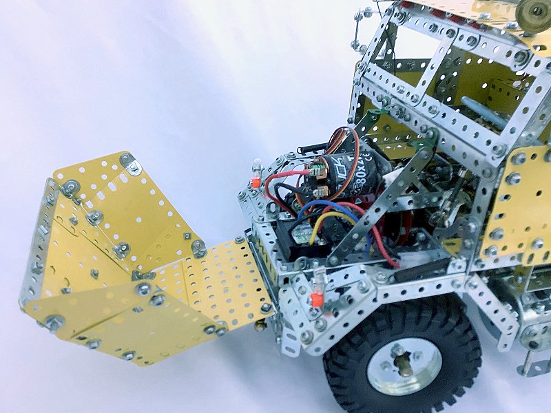
Bonnet open view
Other features simulating door handles, handrails, lights, mirrors, exhaust stack, air conditioning housing, winch operator protection screen and steps were added.
Two R/C-sourced flashing beacons were added to the cab roof (reference 10). They are wired into the winch battery and separately switch controlled.
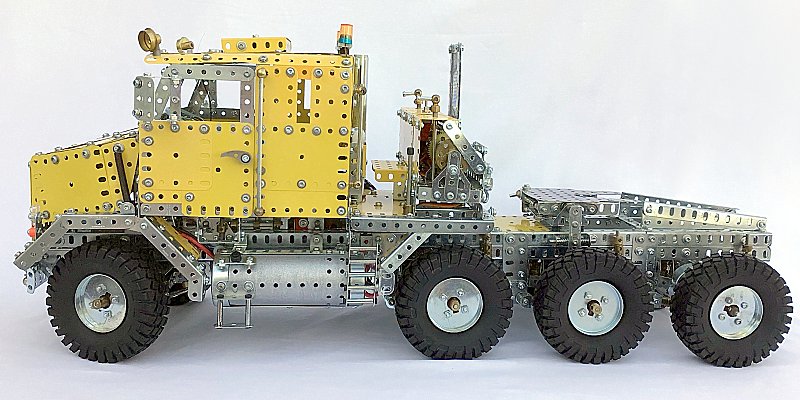
Left-hand side view
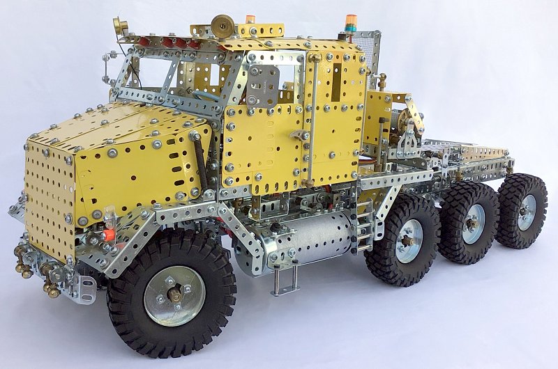
Left-hand side ¾ front view
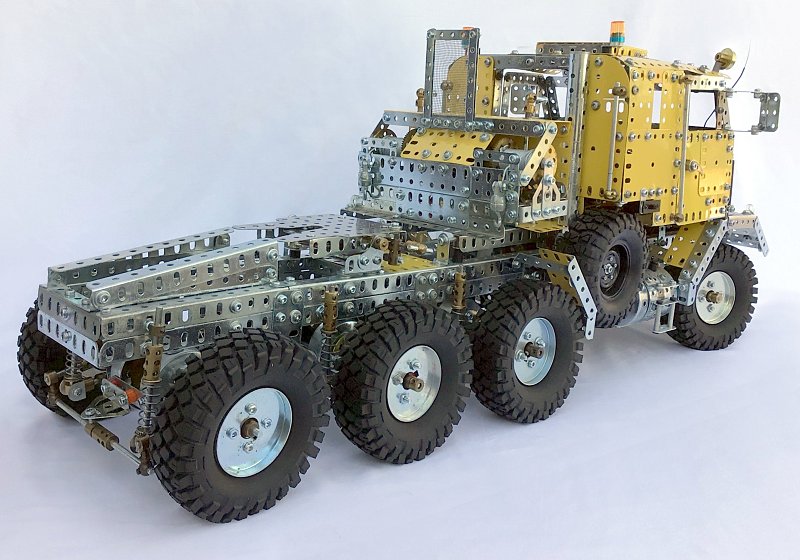
Right-hand side ¾ rear view
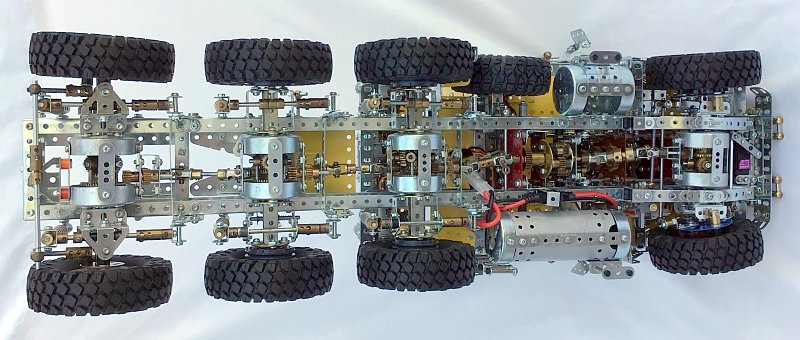
Underside view
The Semi-Trailer
Bogie Steering and Jacking
Work commenced by producing eight more bogies, during which time their design was modified to provide better suspension movement. Not having enough springs (120d), I had to rob springs from the suspension units (120h), which meant that the suspension rates varied slightly for the different bogies. Pairs of bogies were then attached to 9½” angle girders, forming the transverse axle framework of the trailer deck.
As the leading bogie pair (axle № 1) do not steer, they were adapted accordingly.
I happened to have two 36½” long 3 x 1 hole channel girders which, after more scaling work from images and pictures of the prototype and 3D images, proved to be the perfect components for the backbone/spine of the trailer. These were positioned, flanges away from the centre, spaced 1½” apart.
Each bogie is fitted with an axle rod of varying length as a steering arm. The steering arms of the four steerable bogies each side of the trailer are interconnected in series, at different radii, to facilitate the required proportional steering angles at each of the four axles.
The steering linkage is designed in accordance with Ackerman geometry. This linkage would be connected to the tractor chassis for trailer steering control during articulation (figure 11).
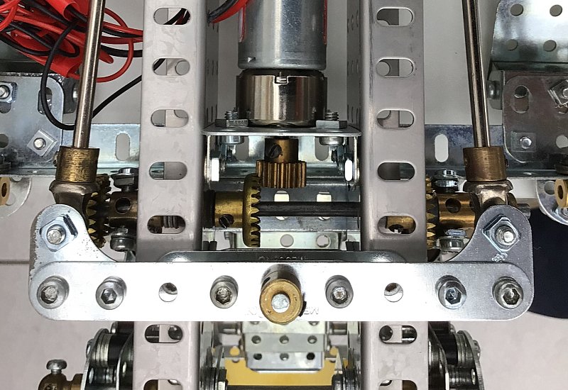
Figure 11 Steering control link
At the crown of each bogie steering axis is a worm and pinion drive for raising and lowering the suspension (figure 12). These jacking drives are connected in series along each side of the trailer (figure 13) and connected to a single motor mounted within the spine. Thus, the whole trailer deck can be lowered for loading and raised for travelling. A DC motor (reference 11) powers the jacking operation.
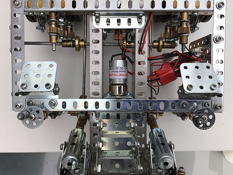
Figure 12 Suspension jacking drive to bogie crowns
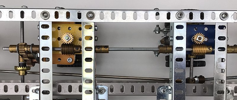
Figure 13 Series connection of bogie jacking drives
Gooseneck
This was the most challenging part of the model to design and construct in order to satisfy the scale and provide sufficient bending strength and stiffness. The tractor’s fifth wheel is 1” higher than scale, so this had to be reflected in the gooseneck. An angle girder framework forms the shape. It is hinged at the connection to the trailer spine to enable equalisation of the load on the fifth wheel. This is achieved via a pair of screw jacks driven by a DC motor (reference 12). Figure 14 shows the gooseneck and deck jacking drives that are powered by a 12V battery (reference 13). The fifth wheel king pin is a 2” sprocket wheel utilising its ½” diameter boss (figure 15).
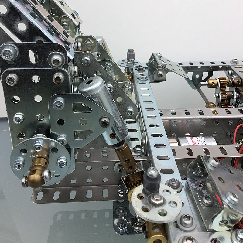
Figure 14 Gooseneck hinge and jacks
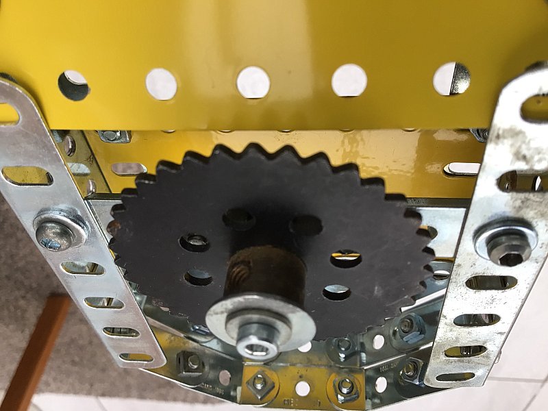
Figure 15 Fifth wheel king pin
A staircase provides access to a hand-operated crane for loading/unloading the spare wheels. Manually operated screw jacks provide ground support of the trailer when it is disconnected from the tractor.
Loading Ramps
The loading ramps are spring-assisted as per the prototype to ease manual deployment and stowing (figure 16).
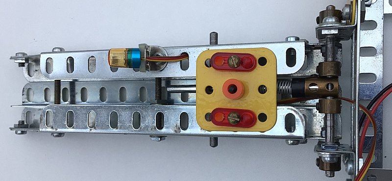
Figure 16 Underside view of one loading ramp showing spring assistance
Two switched flashing beacons were added to the underside of the ramps (reference 14) and are powered by a battery (reference 15).
Electrical Control
A 2½” x 2½” flat plate mounted on the front left-hand side of the trailer was modified to mount two double pole double throw (DPDT) and one single pole single throw (SPST) switches for controlling the gooseneck angle, deck height and warning beacons respectively.
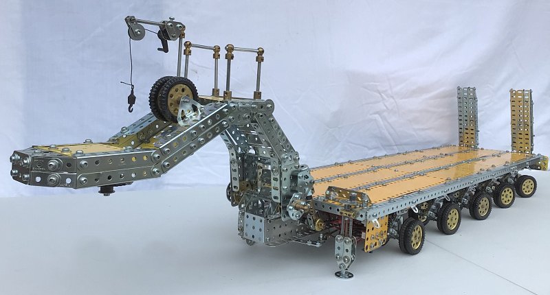
General view of trailer
See more photos of the tractor and semi-trailer.
Appendix 1: Data and Estimate of Model Scale and Dimensions
References
- Traxxas TRX-4 SCXRC4D90 Rock Crawler.
- 3d_molier-International. “Desert Camouflage Oshkosh M1070 Truck with M1000 Semi-Trailer Dirty.” Turbosquid, https://www.turbosquid.com/3d-models/3d-desert-camouflage-oshkosh-m1070–1439912. Accessed 5 July 2025.
- Wenbourne, Alan. “Gearboxes for Beginners — Part 6”. Runnymede Meccano Guild Magazine, issue 83, October 2013.
- Ansmann Racing Truck Motor 80x2T, 80W, 5300rpm at 7.2V DC.
- Mtroniks Viper Marine 15 ESC.
- Ikonnik ET3 Transmitter/Receiver.
- Tower Pro Digital Torque MG996R Servo.
- RadientSuperpax 7.2V 4000mAh 6-cell NiMH Rechargeable Battery Stick.
- Vapextech 5 x AA Cell 6V 250mAh NiMH Rechargeable Battery Pack.
- Sharplace LED Yellow Flashing Beacon.
- Meccparts 6–12V DC Geared Motor 15rpm.
- Meccparts 6–12V DC Geared Motor 167rpm.
- VP Racing 10 x AA Cell 12V 2600mAh NiMH Rechargeable Battery Pack.
- Red Spider LED Yellow Flashing Beacon.
- 6V 400mAh Rechargeable Battery Pack.