Gandy Dancers Railway Hand Car
Written by Alan Wenbourne in February 2026
The September 2025 meeting of the South East London Meccano Club celebrated 200 years since the birth of the modern railway as part of the year-long Railway 200 celebrations. This, not being into trains, posed a problem for me. However, whilst in the USA I acquired a Bachmann G gauge train set for the obligatory ‘around the’ Christmas tree decorations. This set was later expanded for the amusement of visiting grandchildren. Among the additions was a Bachmann Gandy Dancers Hand Car with Trailer, figures and tools, item № 96201, as shown in the box insert below.
The novelty value of this promoted the crazy idea of modelling it in Meccano!
A chassis frame based on the Plastic Strip (B051), 3½” Perforated Strips (3), Trunnions (126) and 1⅛” Flanged Wheels began to formulate. The drive motor would need to be an N20 size gearmotor, of which I had a few.
I decided to shaft mount the motor as it is difficult to attach to its frame. To do this the Ø3mm shaft needs to be lengthened and sleeved up to Ø4mm, which facilitates mounting between two journals. I used Ø3mm inside diameter x Ø4mm outside diameter brass tube for sleeving, with a collar used as a clamp. Later I used stainless steel tube, this being much harder, requiring a socket head grub screw and Allen key to generate the required clamping force, as shown below.
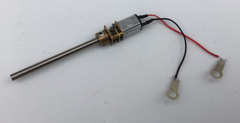
N20 gearmotor
The distortion created when the grub screw is tightened onto the flat of the motor shaft causes the shaft (or motor body in my case) to gyrate when rotated — this runout has to be limited otherwise the motor will stall or work too hard.
A train of 19-tooth pinions connects both wheel axles with a Single Throw Eccentric (130a) on the centre plastic Axle Rod and a fibre washer between it and the 5 hole Perforated Strip. The plastic Axle at one end carries a ¾” Face 19-tooth Pinion (26b) that meshes with a short Worm on the extended motor shaft. Electrical isolation between the chassis members at the other end axle is achieved by attaching the wheels to Threaded Pins (115) screwed into an Electrikit Insulated Spacer (564).
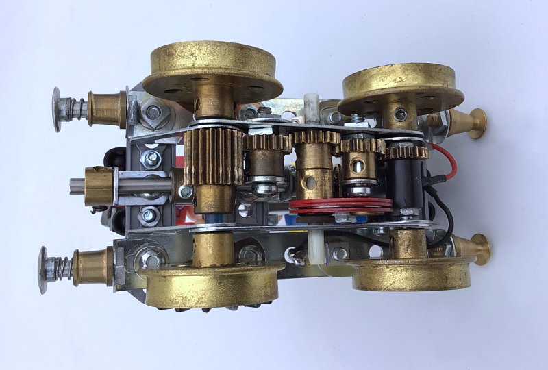
The underside of the model
In this version (Mk1), I experimented with final drive ratios of 1:1 (helical gears) and 19:1 (worm and pinion). The gearbox ratio of these motors is unmarked and therefore difficult to determine, they are generally rated by output speed and voltage. I believe my versions are 100RPM @ 12V.
The helical-geared option was too fast or of insufficient torque, which resulted in the failure of two motors, probably because I was running them on the Bachmann track whose controller outputs 17V DC!
The worm-driven option works but is a little too slow. I added Wiper Blades (532) contacting the wheel flanges to provide extra electrical pick-up at the insulated axle, which enabled uninterrupted operation.
Also, a tip from a Facebook posting suggested using Multi-Purpose Gears (027f_B222) to simulate spoked wheels — brilliant!
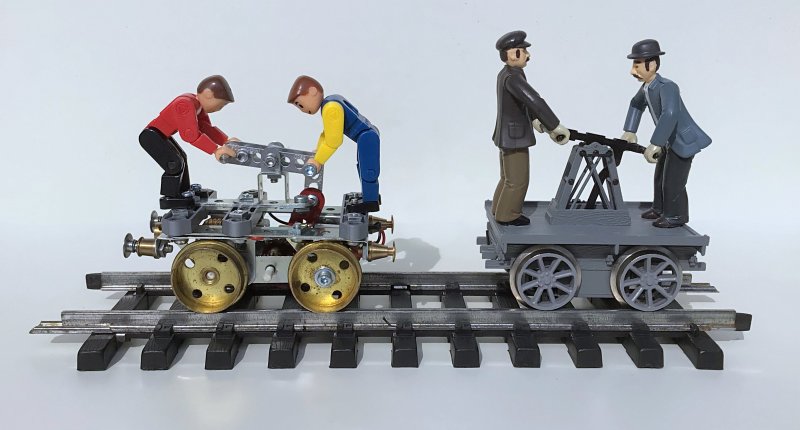
The Meccano Mk1 and Bachmann models
The next stage was to order higher speed motors (500RPM) and set up a length of test track powered up to 12V DC. For this I put together a speed controller with switchable polarity change — something I had wanted for many years! Also, the tedium of having to constantly attend operation by reversing the model before reaching the end of the track was proving too much! What if an onboard double pole changeover (DPCO) switch could be installed to auto reverse at the buffers?
A Mk2 version of the model was built much the same as the Mk1 version except for using a 500RPM N20 gearmotor and Helical Pinions (211a) for the final drive. This ran too fast at 12V but with the speed controller allowing modulation down to about 6V, that speed was more practical.
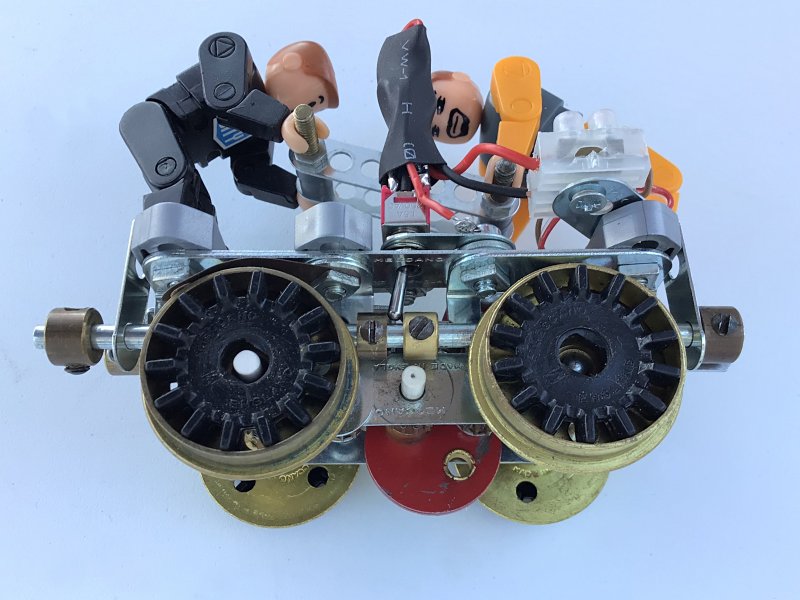
Side view of the Mk2 car showing the switch and control rod for auto-reversing
The next challenge was fitting a sub-miniature DPCO switch, sprung to its (ON)-(ON) positions. This switch is attached to a Fishplate and its lever passed through an enlarged hole in the chassis side frame. A 4½” Axle Rod is journalled through Narrow Angle Brackets (812b) on the same side of the chassis as the switch and is fitted with two Aero Collars (59a) located either side of the switch lever. Collars (59) are fitted each end to protect the switch from over travel and shock load when hitting the buffers. A narrow Fishplate (237) is fitted to the collar at one end to prevent rotation of the control rod.
I had a selection of the miniature Meccano City figures (P023?), which are of perfect size, so I picked the more agile versions and drilled their boots to accept 2.5mm bolts for fastening.
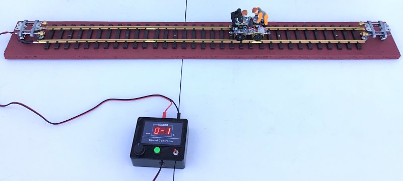
Three feet of G gauge track with buffers, Mk2 auto-reversing car and speed controller
The speed controller consists of the following items from the Component Shop:
- MB3 — ABS Black Project Box with Lid (118 x 98 x 45mm).
- PWM-ESC-DSISP — 20A Standalone DC Motor speed controller with output display.
- SW323 — Sub-miniature Toggle Switch with Double Pole Changeover (DPCO) contacts.
See more photos of this model.