Mini-Version London Eye
Written by Alan Wenbourne for our June 2009 Newsletter
Introduction
The London Eye is an inherently difficult subject to model, not least for the diverse proportions of its elements, in particular the overall diameter of the wheel compared to the size of the capsules which means that if the wheel were scaled down to reasonable tabletop size, the capsules would be very small and hence difficult to reproduce in detail with Meccano. This led me to the concept of a dual-scale model representing a miniature version of the original, hence the term ‘mini’. Such a model could feature a fewer number of capsules than the original, spaced around a wheel of smaller scale than the capsules.
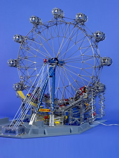
Figure 1 A general view of the London Eye model
Watch our video of this model
Proportions and Scales
The overall proportions of the model would be governed by the size of my car for transportation purposes, which dictated that the model’s diameter would need to be in the range 42–46”. The London Eye is 443ft (135m) high, and I estimated the pitch diameter of the capsules to be 430ft, which, for a model with capsules at about 43” pitch diameter, gives a wheel scale of 1:120.
To illustrate the point made earlier, scaling down the 13-foot diameter London Eye capsules for a 1:120 scale model would result in capsules of 1.3” diameter — too small to reproduce any real detail. My preference was for a model capsule of 3½” diameter (for reasons described later), but at this scale (1:45) the wheel would be 9½ feet in diameter — out of the question! Therefore dual scales suggested a ‘mini’ version of the original might be feasible.
The London Eye has 32 capsules (allegedly one for each London borough). If the model had this many 3½” diameter capsules on a 43” diameter wheel, they would be much too close together. So I considered 16 capsules, a nice number (divisible by 2, 4, 6, and 8) for creating a representative number of wheel spokes and other detail.
Then the concept of taking a ⅜ths segment (135°) of the prototype (embracing 12 capsules) to a 1:45 scale and re-forming that into a smaller wheel was realised. This would create a dual-scale model in which the number of capsules and the ratio of the scales would be proportional, i.e. 3:8 = 12:32 = 45:120, justifying the dual-scale idea.
Twelve capsules are feasible to construct via the use of 12-hole circular discs (for spoke spacing), which had the added attraction of economy of parts and more realistic capsule spacing.
Each London Eye capsule is attached to the rim of the wheel by a sub-frame, which raised the possibility that if the model was designed in modular form, then some or all of the capsules or sub-frames could be detachable, thereby reducing the major dimension for transportation. This would probably be necessary, as it was unlikely that the capsules would be able to support the weight of the wheel, assuming that the wheel would need to be separated from its main supporting structure for transit.
So the major dimensions of 33½” diameter for the outer rim and 38” diameter over the capsule mounting sub-frames was established. The triangular geodetic rim structure would also need to be to the same scale as the capsules, because its width must equate to the capsule’s length.
Challenges
Aside from scale, there are several other challenges to modelling the London Eye:
- Replicating the wheel and rim structure: The London Eye’s wheel rim structure is a triangular truss of circular form, made-up of tubular members, so axle rods would be about the right size based on the wheel diameter scale, but would appear a little slender based on the capsule scale for which ¼” diameter is more realistic. However, if I could roll 5/32” rod into circular form for the inner and outer rims, and if collars could be slid around the rims thus formed, they would provide attachment points for other features. Suitable cross-bracing and spokes could also be constructed with axle rods. The London Eye has 64 cables (spokes) from its hub to the inner rim and 16 rotation cables (8 each side) to the outer rims. Thus for the model with 12 capsules, 24 inner spokes and 12 (6 each side) outer spokes of axle rod size would replicate the cables of the actual wheel.
- Replicating the capsules and their large supporting bearings: My main criterion was that the capsules should be hollow, like the original, which precludes the use of a central axle for rotation. Maybe ½” pulleys rolling inside of a ring of curved strips would work?
- Keeping the capsules level during wheel rotation: This would be a big problem. The possibility of using gravity with under-floor weights or some form of string and pulley or chain drive system, referenced to a fixed pulley at the axis of rotation was considered. Since a hollow capsule was required, there could be no centre axle to apply any form of rotational drive. Gearing was an option using 3½” Gear Rings, but prohibitive for cost reasons. An alternative would be to employ stepper motors under PWM control by sensing wheel rotation and feeding the opposite signal to the capsule levelling motors, but this is not a ‘Meccano’ solution.
- Supporting the cantilevered wheel: Maybe the large-axle system would cope with the overhung (cantilevered) wheel load?
The rest would be easy (as they say!)
Capsule Design
A suitable capsule design became the governing factor in progressing the model further. I soon discovered that pulleys would not roll over the joints of curved strips, so the basis of each capsule became two 3½” Circular Strips (145b) fixed to the frame to form the bearing journals and two 3⅜” diameter rings made up from 2½” Curved Stepped Strips (90a) to which the ½” pulleys and the capsule structure were attached.
During the evolution of a prototype capsule design, weight was concentrated at the floor level by using plastic parts above the axis of rotation, metal parts below and additional ballast weight under the floor. With brass ½” pulleys at the floor level and plastic pulleys overhead, adjusted to roll freely inside the 3½” circular strips, the capsule oscillated quite well, but with the inevitable stick-slip characteristic of static to dynamic frictional resistance. The capsule would only maintain level attitude with intermittent motion, which was not very satisfactory. I considered applying a constant medium frequency vibration through the whole structure to disturb the static friction, but dismissed it as a poor solution, so alternative systems were considered as explained later in this article.
Creating an authentic representation of the capsules’ glass framework was an important consideration. I decided to attempt this using narrow strip parts, which, although they may appear heavier in construction than the actual framework, could compensate for the lack of glass or transparent material.
Using a Meccano strip and plate bending machine and experimenting with rolling various straight and curved strips, the result proved reasonably representative of the actual London Eye capsule glass architecture, as compared in figures 2 and 3.
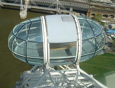
Figure 2 An overhead view of a London Eye capsule showing the glazing geometry
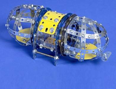
Figure 3 The model capsule, with four pairs of 5-hole narrow strips providing the mounting points
Wheel and Rim Design
A limitation to the size of the wheel was its materials and method of construction. It ought to be possible to roll a complete circle in Meccano-sized rod, but availability and shipping long lengths could be an issue. So I made the decision to limit supplies of rod to 1m lengths, having established availability in ⌀4mm size. Then if the outer rims were made-up in three sections, the metre lengths would allow for the residual straight section left at each end by the rolling process (assuming I could find someone to roll the rods!) to be cut off. The ⌀33½” rim previously considered fitted this requirement admirably, as a third of its circumference is just over 35”.
The outer rims of the model would need to be 7” apart to match the capsule length and the inner rim would need to be about 22½” in diameter. This lead to the notion that if the rim hoops in cross-section formed an equilateral triangle, then 3-hole collars could be used for attaching the cross bracing members, thereby enabling one collar to form a node as the junction of several members. The geometry was altered slightly to enable this.
To develop the idea, a straight section mock-up of the rim was made using 11½” Axle Rods. The peripheral and triangular cross-bracing was replicated using axle rods in rod and strip connectors attached to 3-hole collars at their intersections. Onto this supporting framework a cradle for mounting a capsule was designed and constructed using narrow strips and angle girders, the frame legs being stiffened with axle rods in rod and strip connectors. Development of the circular form of the wheel, shown in figure 4, followed as shown in figure 5, the assembly of which is described later in this article.
Figure 4 The London Eye capsules, capsule mounting framework and circular wheel truss
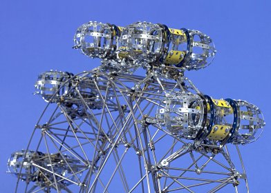
Figure 5 The model capsules, capsule mounting framework and circular wheel truss
Capsule Levelling System
The need for a powered capsule-levelling drive system became obvious. A cord or chain system was discounted due to the lack of a sufficiently large ‘hollow’ pulley or sprocket in the Meccano system. Some research indicated the availability of less expensive 3½” Gear Rings (180), which could prove valuable in devising a mechanical levelling system, so this approach was pursued.
The concept was of a fixed 3½” ring gear located at the wheel rotation axis, which, through 1:1 ratio gearing connected to the individual gear rings at the capsules, would maintain the capsules in level attitude. To avoid the need for twelve radial drives from the wheel hub to the capsules, I chose to use four radial drive shafts at 90° angular spacing, each driving every fourth capsule through contrate and pinion gearing. Additional bevel gearing transfers the drive circumferentially to the two capsules fore and aft of the driven capsule. Figure 6 shows one capsule levelling drive and mounting frame.
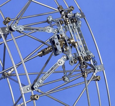
Figure 6 The capsule mounting frame with radial and circumferential drive arrangements — the four collars are the capsule attachment points
Wheel Hub
The hub of the wheel needed to be fairly robust, so large-axle parts were adopted as the main supporting members. Having no idea how heavy the wheel would be, I hoped that a large-axle rod would be able to carry the weight of the cantilevered wheel. To simulate the proportions of the London Eye hub, two Boiler Centres (162b) are joined together, capped with Wheel Flanges (137) arranged between two ⌀2½” 12-hole Circular Plates (146h) spaced 7” apart to form the hub flanges.
The circular plates needed to be indexed 15° to each other to provide 24 spoke mounting holes (12 each side) alternating from side to side. This was achieved by mounting the 12-hole circular plates to 8-hole Large Bush Wheels (253) that are connected together by four 8” Screwed Rods (79), the bush wheels being one hole out of phase. This gives the required angular spacing by the difference between the hole spacing of the bush wheels minus that of the circular plates i.e. 45° − 30° = 15°.
A ⌀3½” Wheel Flange carrying the four capsule drive contrate and pinion gear sets is attached to the 8” screwed rods at the support side of the wheel and provides the four radial driveshafts to the capsules via Universal Couplings (140), as shown in figure 7.
Spindle Housing
The spindle housing is built-up from a 9-hole Long Cylinder (163b), an 11-hole Long Sleeve Piece (163d) and 11-hole Perforated Strips (2) that form the tapered feature. Both ends carry 8-hole Large-Axle Bush Wheels (253) combined at the wheel end with a 2½” Circular Plate (109a) that is extended with strips and spacers to carry the central fixed Gear Ring (180). An extra long large axle rod (⌀ 8mm × 17”) is journalled through and fixed to the spindle housing to form the wheel axle. The lower underside of the spindle is fitted with trunnions and brackets for attaching to the supporting ‘A’ frame and cable stays. Figure 7 shows the assembly.
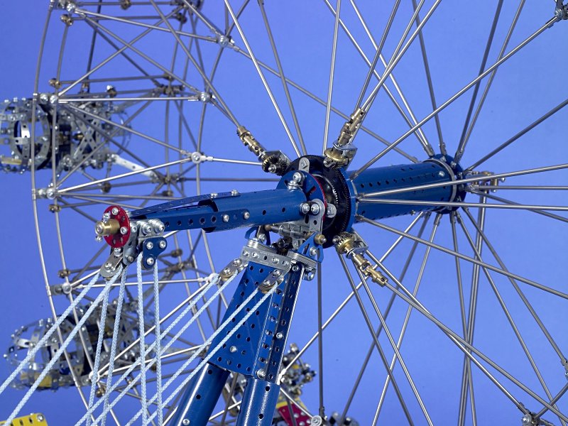
Figure 7 The spindle housing, wheel hub, cable stays and inner ends of the capsule drives
Support Columns
The London Eye has two tubular steel main supporting columns forming an ‘A’ frame that sits on trunnions mounted upon tall concrete pillars supported by 44 concrete piles 33m deep. This ‘compression’ foundation contains 2,200 tonnes of concrete.
In the model the pillars are made from angle girders, which are screwed to the baseboard. The columns are four back-to-back 31-hole Angle Girders (7b) encased in one 7-hole and two 11-hole Cylinders (216a and 216c) each. Trunnions built-up from triangular plates form the mounting supports.
Wheel Construction
The wheel geometry was drawn full size in layout form onto a 4ft square MDF board for use as a template for bending the circular components and for marking the joints and connection points (nodes) of the cross-bracing.
Initially, 15 one-metre lengths of ⌀4mm stainless steel rod were purchased for the wheel hoops, which were rolled to the approximate radius. These were formed to the actual radius by hand-bending against the layout, and then cut to length to form the 120° arcs of the outer rims. Short Couplings (63d) and 3-hole Collars (59b) were fitted to each section before joining with Couplings (63). The inner hoop was similarly constructed except that it is formed in two 180° arcs. Having succeeded in fabricating the hooped rims to an acceptable degree of accuracy (within ± 1/16” circularity), the remaining 46 one-metre lengths of 4mm rod were purchased to make the spokes and cross-brace members.
The layout was then converted to an assembly fixture, by adding six notched support brackets to locate the two outer hoops in their correct position, for fitting the transverse cross-bracing and locating the 3-hole collars at their correct node points. Short couplings journal the rods parallel to the axis of the wheel and hold the outer rims at the correct distance apart, reflecting similar features in the London Eye structure. The external diagonal bracings are lengths of rod cut to size and fitted with Rod and Strip Connectors (212) at each end. These are spaced to interlace with each other and the axial bracing, and secured to the node points with ½” Bolts.
The assembly fixture was then modified to provide support and location of the inner hoop of the rim, enabling the radial cross-bracing to be built-up. A large-axle sprocket, screwed to the centre of the board, provided a journal for location of the hub during assembly of the spokes. Figures 8.1 to 8.4 show the principle stages of assembly.
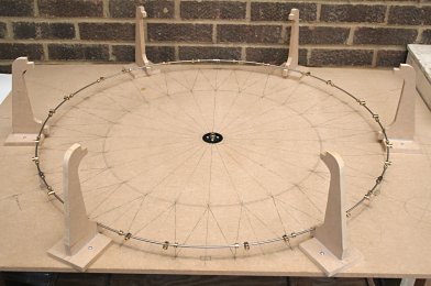
Figure 8.1 Wheel assembly fixture with one outer rim
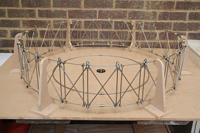
Figure 8.2 Outer rims and cross-bracing assembled
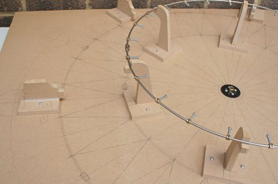
Figure 8.3 Inner rim in place
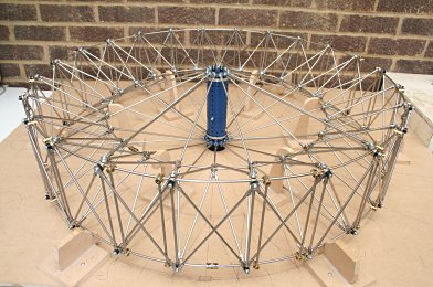
Figure 8.4 Completed wheel and hub assembly
Initial Erection of the Wheel
The ‘A’ frame and spindle housing were erected as a temporary structure, with long perforated strips to simulate the backstay cables, and the wheel (without capsules) mounted onto a long 5/16” diameter stainless steel rod extending from the spindle housing. The resultant deflection due to the 25lb weight of the cantilevered wheel was alarming! A higher strength rod (high tensile) would not help as all grades of steel have the same modulus of elasticity, so this became a serious problem.
An outrigger bearing was an obvious option so that the wheel would be straddle-mounted on the large-axle rod forming a simply supported beam. This would be a pity because one of the main features of the London Eye is its cantilevered design.
A pair of large built-up bearings would be a possibility, but not favored, mainly because of problems I could foresee with dismounting the wheel for transportation. Reluctantly, I decided on using a prop, but just to keep the axle (spindle) level and not to provide any lateral constraint.
Drive Machinery
The London Eye is driven by pairs of car-type rubber-tyred wheels which engage with steel box section drive tracks welded to the main outer circular spars. There are four drive sets — two each side of the wheel, positioned on the downstream river (North) edges. Each drive set consists of four driving wheels — two above and two below the drive track. A hydraulic motor gearbox on the drive wheel axis attached to an oscillating arm powers each driving wheel, which is allowed to float vertically to compensate for any variations in drive track (these are actually 64 straight box sections). These pairs of drives are arranged back-to-back to form the sets of four drives, as shown in figure 9.
With sixteen driving wheels altogether, any speed variation is compensated for by the hydraulic flow to the motors (hydraulic differential effect). The plethora of driving wheels is to provide redundancy — only two drive sets are actually required for normal operation and only one set for emergency operation.
The driving wheels do not support any component of the wheel’s weight. There are additional wheels or rollers, bearing on the sides of the drive track — these are part of the rim guidance system to provide lateral (axial) stabilisation of the wheel.
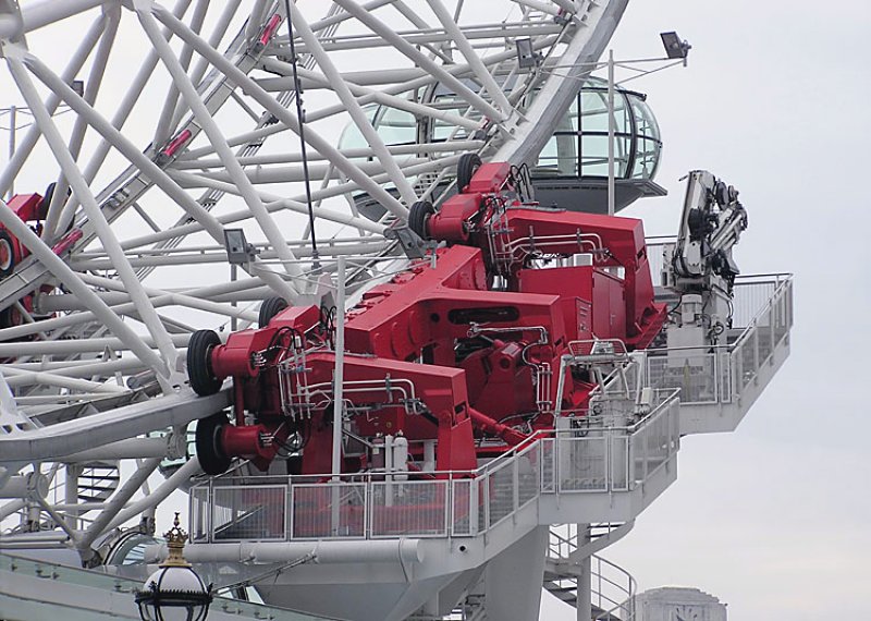
Figure 9 The London Eye drive machinery deck located at the north-east corner of the wheel
These guide wheels also control movement due to wind and deflection at the boarding platform level. A similar layout of guide wheels is repeated on the up-stream (south) edges of the wheel but without drive sets. The drive and guide wheel sets are mounted on towers at each ‘corner’ of the structure’s footprint.
All of the drive machinery is painted red.
Located at the centre of the ‘tee’-shaped structures carrying the guide rollers are retractable locking pins which can engage in holes in the sides of the drive tracks. During normal operation the pin assemblies are lowered, away from the drive tracks, by hydraulic rams positioned inside and underneath the machinery platforms. These safety-locking devices are used during high wind conditions or maintenance work — I have not replicated these in the model.
The drive tracks in the model are 33½” diameter secondary rings of ⌀4mm rod, each made up in three pieces joined with Rod Connectors (213) and attached to the main wheel outer spars by 12 Right Angle Rod and Strip Connectors (212a) on each side.
Pairs of rubber-tyred (452) ½” pulleys (23a and 23b) are used as driving wheels on 2” long arms enclosing a train of 19-tooth pinions, as shown in figure 11. These are mounted onto a gearbox in opposed sets of four and spring loaded with Shock Absorbers (120d). Since the rim in the model is a round rod I have used twinned wheels for better traction and guidance.
Each gearbox contains a pair of 38-tooth Gears (31) and 4:1 reduction gearing from the motor input, as shown in figure 12. The drive motors are 37rpm geared motors from Meccparts. There is one for each drive set, wired in parallel in order to provide speed compensation for when individual wheels roll over the rod connectors.
As I needed to remove the main wheel for transportation, I made the driving wheels retractable by means of a linkage mechanism to all four wheels of each drive set, controlled by a locking lever mounted between the pairs of drive wheels, as shown in figure 10.
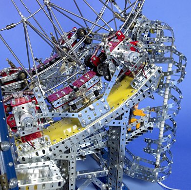
Figure 10 The two drive sets (in the foreground), the drive wheel disengagement controls and the retractable guide wheels
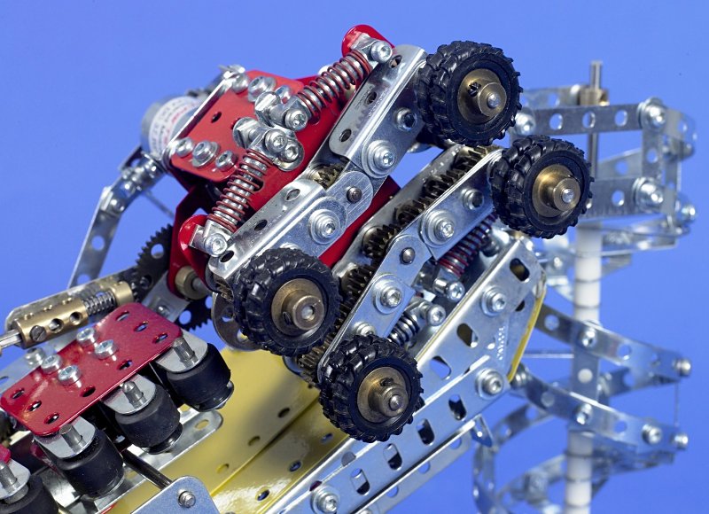
Figure 11 A detail view of one drive wheel set showing the 19-tooth pinion gear trains
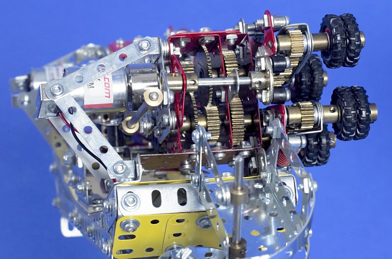
Figure 12 An end view of one drive wheel gearbox, also showing the wheel retraction device
Rim Guidance System
In the model there are four sets of guide rollers, two positioned between the main drive assemblies, and one between and one opposite the electrical pick-up gear, the latter seen in figure 13. Each set has six guide rollers consisting of ⌀⅝” Tyres (142m) mounted on Plastic Spacers (38a) carried in Double Bent Strips (11a). These have Long Threaded Pins (115a) fitted with Compression Springs (120b), set at ¾” spacing in a box-shaped housing. The springs allow the rollers to pass over rim connections whilst maintaining contact with the wheel drive track for axial stability. Each set of six guide rollers is mounted on a retractable frame in order that they can be moved out of the way for dismounting and extracting the main wheel from the drives.
Electrical Pick-up
The London Eye south-west (river-side) machinery platform has two sets of electrical brush gear, one operational and one for backup or maintenance. The brushes are sprung-loaded onto a five track bus bar which runs around the periphery of the main wheel rim structure. The brush spring force is reacted by two small wheels running on the inner side of the drive track. The brush gear sets are attached to linkages that compensate for undulations in the drive track profile and a retracting linkage for maintenance.
Although the model does not feature electrical pickup, this equipment is replicated in the model as shown in figure 13, with pairs of wheels running above the track and a dummy five-gang brush arrangement outside the track. Compliance and retraction linkages reflect the geometry of the actual mechanism.
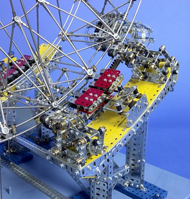
Figure 13 The replica electrical pick-up brush gear
Gangways and Spiral Maintenance Access Stairs
The London Eye has a plethora of access walkways for maintenance purposes, all of which are suspended over water, as the machinery deck foundations are in the riverbed. I chose to reproduce just one set at the drive platform end. This consists of a stairway from the boarding platform to halfway up the east machinery deck spiral stairway — this also connects to the west machinery deck, via another gangway and spiral stairway, as seen in figure 14. Since these involve much bending of parts, I decided one set (shown in figure 15) would suffice in the interests of saving money and avoiding mutilation of parts!
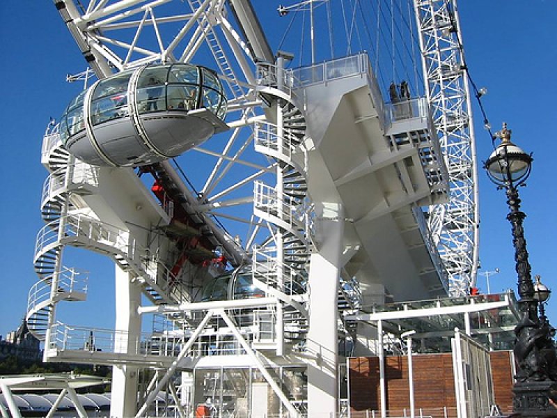
Figure 14 The maintenance access walkways on the south side of the London Eye
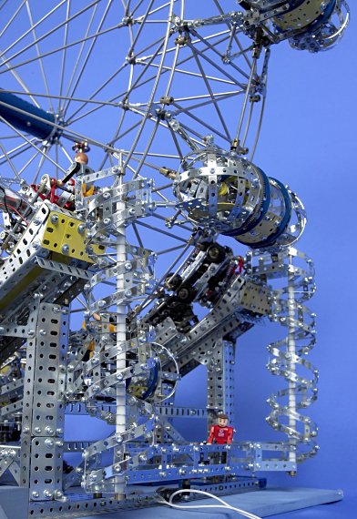
Figure 15 The maintenance access walkways of the model installed at the north machinery towers
Backstay System
The six London Eye backstay cables, four to the top of the ‘A’ frame and two to the tail of the spindle housing, are anchored to a 1,200 tonne underground concrete ‘tension’ foundation. The cables are protected above ground by security sleeves, a glass walled housing and concrete pillars, as seen in figure 16.
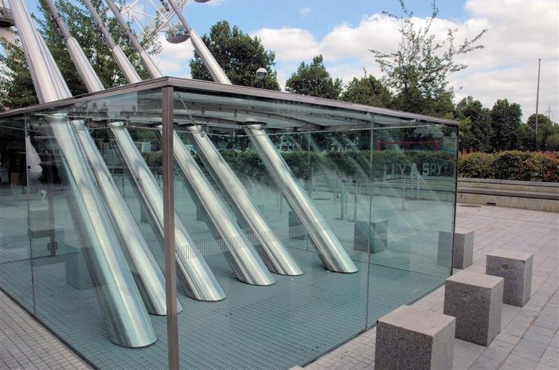
Figure 16 The backstay cable and protection arrangements of the London Eye
Figure 17 shows the representation of these features in the model using ⌀⅛” nylon cord anchored to Meccano couplings and turnbuckles. The backstay cords are sheave strung to equalise tension.
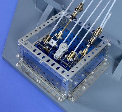
Figure 17 The backstay cord anchorage and tensioners in the model
Boarding System
Figure 18 shows the ramped exit aisles on the left and entrance ramps on the right. These lead to and from the disembarkation and boarding platforms respectively that are curved to match the arc described by the step on the capsules.
Figure 18 The entrance/exit, boarding and disembarkation platform module
Wheel Speed
As the model is dual scale, and time passes quicker in the model world, determining the best speed of operation posed an interesting dilemma. The London Eye rotates once every 30 minutes (0.033 rpm), which for a model at 1:45 scale equates to 0.22 rpm or one revolution in 4.5 minutes. At the 1:120 scale, the model speed should be 0.37 rpm or one revolution in 2.7 minutes. I decided it would be more realistic to base the speed on the capsule scale. The selected motors and reduction gearing, operating under load, give a wheel speed very close to 4.5 minutes per revolution.
Model Assembly and Transportation
The modular design allows relatively easy breakdown and re-erection. The restraining cord anchorage remains on the board with the ‘A’ frame support strapped to it. The two sets of machinery towers/platforms and the entry/exit-boarding platform are separate modules. The capsules are removable, being attached to their wheel mounting frames with four plastic Pivot Axles (260d) each. The wheel (less capsules) is laid flat, supported peripherally on battens integral with the board and located centrally by a large axle rod.
Significant Parts Count
- 600 Rod and Strip Connectors (212)
- 144 Collars (59)
- 134 ½” Pulleys (23)
- 120 Narrow Angle Brackets (239)
- 96 11-hole Narrow Strips (235f)
- 96 Curved Stepped Strips (90a)
- 72 19-tooth Pinions (26)
- 72 3-hole Collars (59b)
- 48 Right-angle Rod and Strip Connectors (212a)
- 28 Short Couplings (63d)
- 36 Single Arm Cranks (62)
- 24 Universal Couplings (140)
- 13 Gear Rings (180)
- 210ft (64m) of ⌀4mm SS rod
See more photos of this model.