Nile Barrage Lifting Bridge at Assuit
Written by Alan Wenbourne for our March 2010 Newsletter
Whilst musing over what to build next, I wondered what was on the front cover of the Meccano Magazine of my birth month?
It is a lifting bridge at Assuit in Egypt, forming part of the Nile barrage system, 300 miles downstream of the Aswan dam. The bridge provides a crossing and passing point for road and river traffic at a lock to one side of the dam.
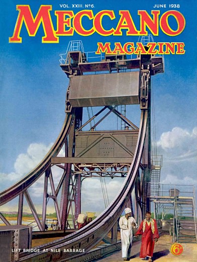
A picture of the bridge on the Meccano Magazine cover
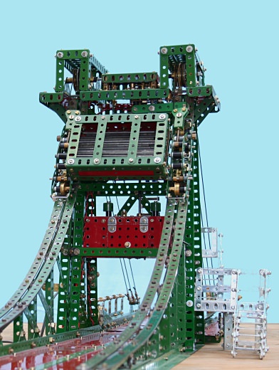
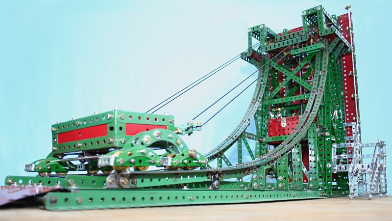
The same view of the model bridge (minus the locals!)
At first sight, it did not inspire me very much, being just another bascule type bridge! However, reading the article made me aware of its unique features and I began to warm to the idea of modelling the subject — I was surely destined to attempt this model!
Its unique feature is the rolling counterweight, running on a variable sloped track, shaped to maintain constant balance in the cables that connect the counterweight to the bascule section and which pass over pulleys at the top of the tower.
The basis of its operation is that when raised, the hoist cable tension is minimal, as the hinge points carry the bascule weight. Only a small out-of-balance component remains due to the hinge offset, this being necessary to overcome friction and ensure the bascule is biased to lower naturally. In this position, the counterweight is on the minimum slope of the track, imposing minimal hoist cable tension and maximum load to the track. In the lowered position, the bascule hoist cable tension is at maximum, due to the weight transfer of its centre of gravity and the angle posed by the hoist cables. This is when the counterweight is virtually vertical, applying maximum hoist effect and minimum load to the track. Therefore, if the slope of the track between these extremes can be calibrated to ‘balance’ the tension in the hoist cables, then only minimal and virtually constant power is required for its operation.
Watch our video of this model
The initial challenge would be the mathematical analysis to determine the coordinates of the track profile.
The article in the June 1938 issue of Meccano Magazine gives a very good account of the bridge’s engineering, structure and proportions, supported with pictures. I considered using 18½” angle girders for the opening span, so based on the 60 foot span of the original, a scale of 1:40 was established. Scaling the pictures determined the other proportions.
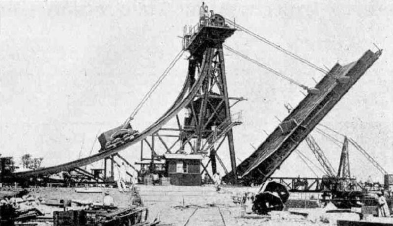
A photo of the bridge from page 307 of the June 1938 issue of Meccano Magazine used for scaling the bridge proportions
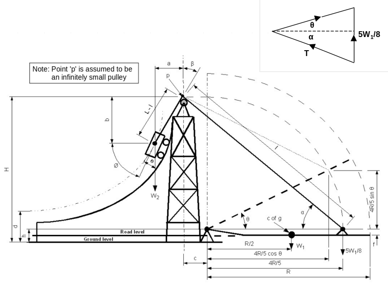
Figure 1 Dimensions and weights of the 1:40 scale model, and the vector force diagram (inset)
I set up a spreadsheet with dimensional and physical variables into which I could insert either full-scale or model-scale values to test and calculate the unknown properties, i.e. weights and track geometry. The final results were calculated as follows (with reference to the dimensions and weights shown in figure 1):
a(min) = 3.5”
b(min) = 5”
c = 3.5”
d = 2.88”
e = 1.63”
f = 1”
h = 1.75”
H = 17.75”
L = 30.56” (note that L is the total length of hoist cable from bascule to counterweight)
R = 18.75”
W1 = 4.4 lbs
W2 = 4.2 lbs
Mathematical analysis:
I = [(4R / 5cosθ + c)2 + (H − h − 4R / 5sinθ)2]½
α = atan[(H − h − 4R / 5sinθ) / (4R / 5cosθ + c)]
By sine rule (with 6.08° allowance for position of centre of gravity offset (f) from fulcrum):
T = 5W1sin(90 − θ) / 8 / sin(θ + α)
For bascule down:
a = 3.5”
b = 5”
L − l = 6.1”
Therefore at Θ = 0:
L = l + 6.1 = 30.56”
ß = atan(3.5 / 5) = 34.992°
For bascule up:
b = 17.75 − 3.38 = 14.37”
L − l = 30.56 − 3.64 = 26.92”
Therefore:
ß = acos(14.37 / 26.92) = 57.737°
Intermediate values of ß are obtained graphically by establishing incremental points of tangency.
The coordinates for plotting the path of the counterweight centre of gravity are:
a = (L − l)sinß
b = (L − l)cosß
By cosine rule:
Fn = (T2 + W22 − 2TW2cosß)½
By sine rule:
ø = sin-1(Tsinβ / Fn)
Based on the dimensions of the actual bridge, I calculated incremental tension forces in the balancing cables connecting the counterweight to the bascule, based on the quoted counterweight mass of 65 tons and an unknown mass (W1) for the bascule. Then, for these increments of bascule lift angle, I formulated expressions for the coordinates and slope of the track. This proved to be far more challenging (and time consuming) than I had imagined, but eventually I arrived at some sensible values which appeared to validate the procedure.
| Angle of bascule to horizontal (°) |
θ |
= |
0 |
15 |
30 |
45 |
60 |
75 |
90 |
| Length of hoist cable, bascule side (”) |
l |
= |
24.459 |
21.690 |
18.552 |
15.102 |
11.404 |
7.535 |
3.640 |
| Angle of bascule hoist cable to horizontal (°) |
α |
= |
40.855 |
33.965 |
25.290 |
20.923 |
15.302 |
11.568 |
15.900 |
| Tension in hoist/counterbalance cable (lbf) |
T |
= |
4.18 |
3.60 |
3.06 |
2.34 |
1.67 |
0.99 |
0.30 |
| Length of hoist cable, counterweight side (”) |
L − l |
= |
6.10 |
8.87 |
12.01 |
15.46 |
19.16 |
23.02 |
26.92 |
| Angle of counterbalance hoist cable to vertical (°) |
β |
= |
34.992 |
32.700 |
35.000 |
39.700 |
45.200 |
50.800 |
56.470 |
| X axis counterbalance centre of gravity coordinate (”) |
a |
= |
3.499 |
4.792 |
6.887 |
9.874 |
13.592 |
17.843 |
22.440 |
| Y axis counterbalance centre of gravity coordinate (”) |
b |
= |
4.998 |
7.465 |
9.836 |
11.893 |
13.498 |
14.552 |
14.870 |
| Reaction force normal to track (lbf) |
Fn |
= |
2.520 |
2.270 |
2.439 |
2.826 |
3.246 |
3.655 |
4.200 |
| Instantaneous slope of track (°) |
ø |
= |
72.076 |
58.998 |
45.980 |
31.985 |
21.473 |
12.126 |
3.447 |
Serious modelling then started, with the bascule first, followed by the tower and the connecting hinge brackets. The bascule hinge points are offset vertically and it has cantilevered pedestrian footways on each side.
The tower consists of back-to-back 15½” angle girders at each corner, cross-braced in accordance with the original.
The actual bridge has a machinery cabin 20 feet above the road level, housing a variable displacement hydraulic pump driven by an electric motor. The hydraulic power is conducted through pipework to the top platform where hydraulic motors split the power mechanically to cable drums on either side for hoisting the bascule.
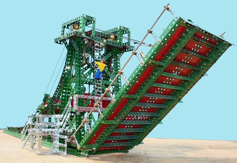
A view of the model from the lock aspect, with bascule partly raised
The model has an electric motor in a housing 6” above the roadway. This drives a vertical rod via pinion and contrate gearing to the top platform. A rubber rod connector allows slip as overload protection in the vertical drive.
Whereas the prototype bridge uses hydraulic flow division for differential effect, I used a mechanical differential to maintain equal tension in the hoisting cords.
Pairs of cords each side connect the counterweight to the bascule, passing over 1½” pulleys free mounted on axle rods, at the top of the tower. Between each pair of pulleys is a gear-driven hoist drum.
The model bascule was weighed at 4.4 lbs. This value and the model dimensions were entered into the spreadsheet and the resultant track geometry (curve) was drawn full scale to check feasibility. The curve proved to be somewhat incompatible with the tower proportions, so the spreadsheet and calculations had to be reviewed and modified, because I was not about to re-build the tower!
A second set of coordinates and slopes were drawn up and seemed in order. All this was necessary to avoid resorting to trial and error when constructing the curved track and it’s supporting structure.
The design of the track depended on the type of counterweight running gear, so this was tackled next.
Ground level view of the model with bascule in raised position
The prototype counterweight is a steel box filled with iron and concrete, with reserve capacity for fine-tuning on testing. So a scale box was constructed, with the object of filling it with axle rods (and hoping it would be large enough!)
Four oscillating bogies were designed as close to the originals as the detail in the pictures conveyed, wuth ¾” flanged wheels forming the running gear. Arched connecting members each side of the box carry the bogies, and the box is tri-mounted to maintain wheel contact with the track to compensate for any irregularities.
Each bogie carrier is fitted with adjustable and pivoted drawbars.
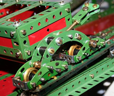
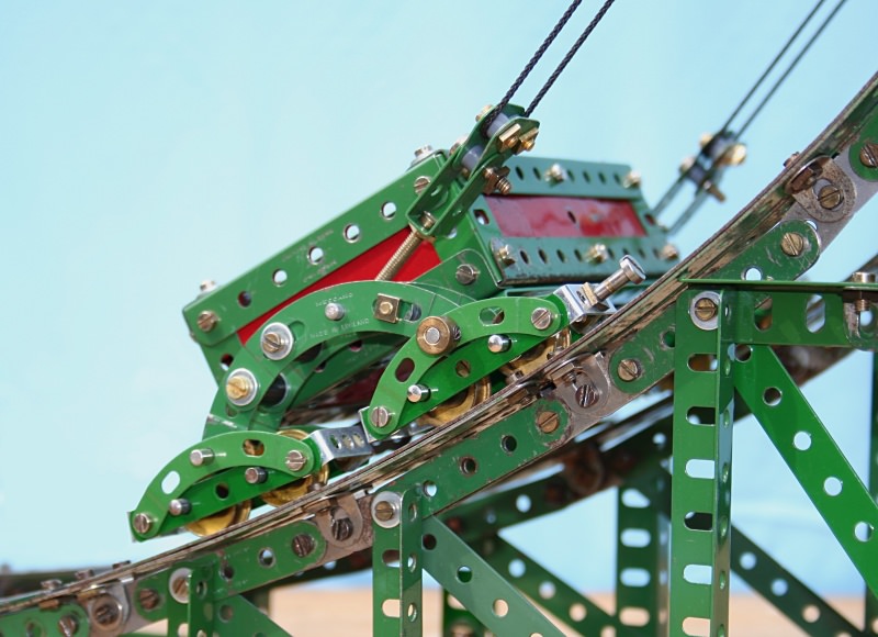
Close-up of the truck and bogie arrangement
The track was then constructed by bending (old) 12½” and 5½” strips to shape against the layout curve. These were connected together with angle brackets, fishplates and segmental strips to form a ‘T’ section for stiffness, and spaced 5/32” apart to guide the wheel flanges. A supporting structure for the track was then constructed along the lines of the original.
At the outset, I had considered using countersunk track-securing screws to avoid the bogie framework and wheels fouling regular bolt heads. However, I decided against this non-Meccano/mutilation solution by using setscrews (smaller heads) to fasten the track strips. Unfortunately the original bogie wheel frames made from standard strips just caught the screw heads towards the top of the track, where the curve tightens. This resulted in a complete re-design of the bogies using narrow strip parts to increase clearance with the track.
The truck (counterweight assembly) was then run up and down the track and a few minor adjustments made to achieve smooth running before connecting the balance cords. Despite having estimated the truck rolling resistance and allowing for this in the
spreadsheet calculations, the physical test revealed that the lower slope was too shallow to allow the truck to run to the end of the track. The slope at the lower end is critical, as it has to be steep enough to overcome the trucks rolling resistance, but not so steep that the force needed to start its ascent would prevent the bascule lowering under its own weight bias. Having increased the slope at the end of the track slightly, this is exactly what occurred. The solution adopted was to add spring-loaded plungers between the tower and bascule to assist the initial lowering motion.
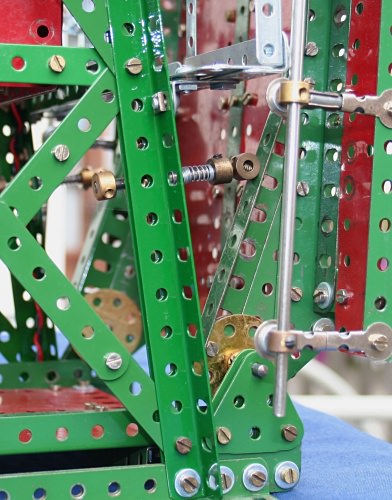
One of the lowering-assist plungers
The winding mechanism was then strung with cord and the bascule operated under power. Further minor adjustments and lubrication ensured effective working.
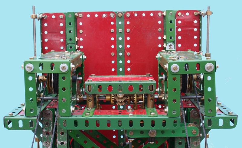
The differential splits the drive to each winding drum via 15-tooth/60-tooth gearing
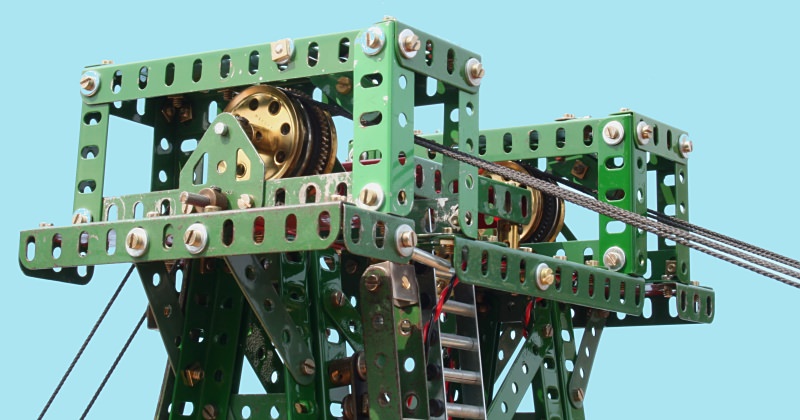
View of the balance cable, head pulleys and winding gear
The maintenance access stairway and ladder structure were constructed using zinc parts to replicate the apparent white or galvanised finish of the original shown in the Meccano Magazine cover picture.
To enable automatic termination of the raise and lower movements, Elektrikit limit switches were added and an Elektrikit knife switch mounted on the side of the tower for reversing the raise/lower function.
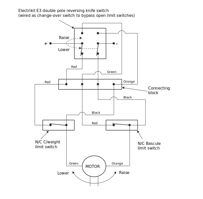
Figure 2 The bridge control and switching circuit diagram
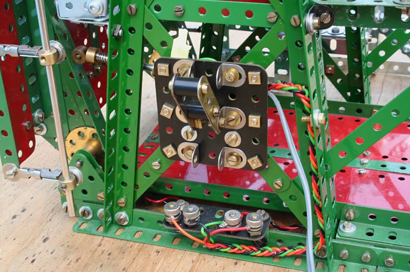
The Elektrikit knife switch for raising and lowering
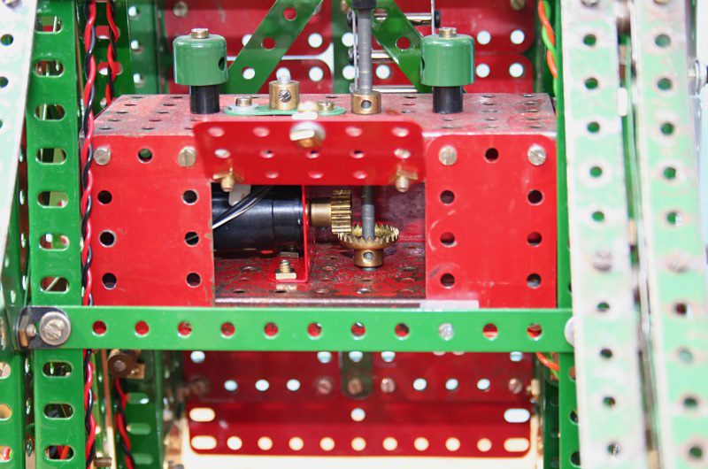
The motor housing and vertical drive shaft
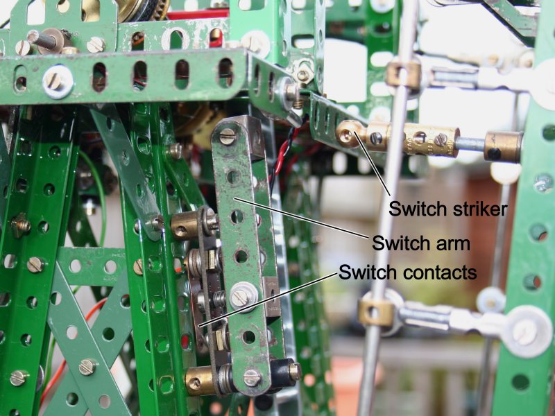
The ‘bascule raise’ limit switch.
Track detail and ‘bascule lower’ limit switch striker (Pivot Bolt)
The complete model, apart from the electric motor, is constructed in Meccano — albeit a strange mix of old, new, red, green, zinc and replica parts.
See more photos of this model.