March 2005 Newsletter

March 2005 Newsletter
Issue 114
This was one of our informal quarterly meetings where our members showed off their latest Meccano creations.
At around 2:00pm we had a short committee meeting, followed by the Model Tour in which members were invited to give a short talk about their models — in particular their entries for the Secretary’s Challenge!
Written by George Foard
Recently I read an article on the 1915/16 Fokker Eindecker aircraft and how it was powered by a variety of Oberursel rotary air-cooled engines. I thought a small model of the seven-cylinder version was a suitable challenge. So, to while away the many hours over the holiday period, I set to.
To begin with, aircraft-type radial engines, be they rotary or integral, are, in the main, of an odd number of cylinders. Be they 3, 5, 7, 9, 14 (2x7), 18 (2x9) and 28 (4x7). Through many years of test and trial an even number has been found to be too complicated an unreliable.
In various Meccano/Hornby journals these engines, when built, seem to have an even number of cylinders. I may be wrong — if so I stand to be corrected.
However, off we go! Eventually I succeeded with a seven-cylinder model.
In the Meccano system small perforated wheels, i. e. 24s, 24Bs and 518s have six or eight holes — evens.
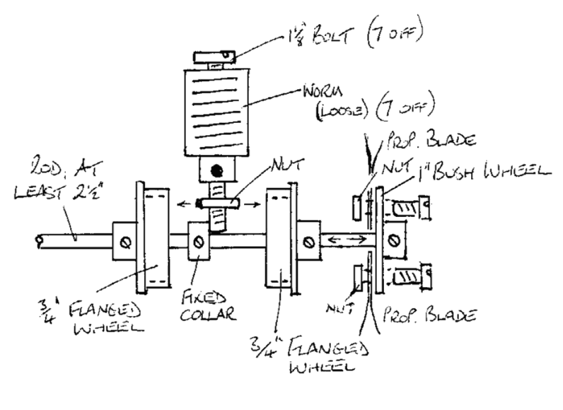
Figure 1 7 Cylinder Rotary Engine — side elevation
So:
- Take seven worms (32), 11/8” bolts (111D) and nuts to fit. Insert the bolts through the worms from the business end and attach the nuts loosely at the boss end.
- Choose a suitable length of axle rod (I used a 2½” 16A) to mount everything on. A ¾” flanged wheel (20B) is locked to the rod about ½” from one end, boss outwards. Next on the rod is a collar with grub screw (59), locked on the rod almost within the “dish” of the flanged wheel at such a distance from it as to retain the end of a 11/8” bolt in a lateral position, (see diagram, below). Each of the seven bolt ends with nuts rest within the flange of the ¾" wheel — just — provided the nuts are ‘squared’ to each other.
- Place a second ¾” flanged wheel on the rod, flange facing the first one so as to lock itself over the retained bolt-ends and nuts and tighten. It can be done with a bit of jiggling.
- Each of the 11/8” bolts may now be tightened up, carefully. Slight adjustment may be necessary to give alignment.
- To complete the little engine, bolt two propeller blades (41) at the correct pitch on the flat side of a 1” bush wheel (518). Some filing may be necessary on the ends of the blades to clear the rod. (Sorry, but it makes a better job).
- Finally, mount the engine, by way of the rod, on a suitably strong backing plate so as to revolve. I used a bush wheel (24) bolted to a semi-circular plate (214). The whole engine may be mounted on a suitable display stand.
I have used grub screws on all the bosses as they are less obtrusive.
P. S. The direction of the rotation should be anti-clockwise if you have tweaked the blades to the correct pitch.