Hand-Generator Car
Written by Brian Elvidge for our April 2002 Newsletter
The idea for this model came from one similar built by Nigel Pope and seen at the SELMEC exhibition at Bromley in 2001.
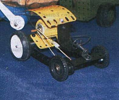
Nigel Pope’s version
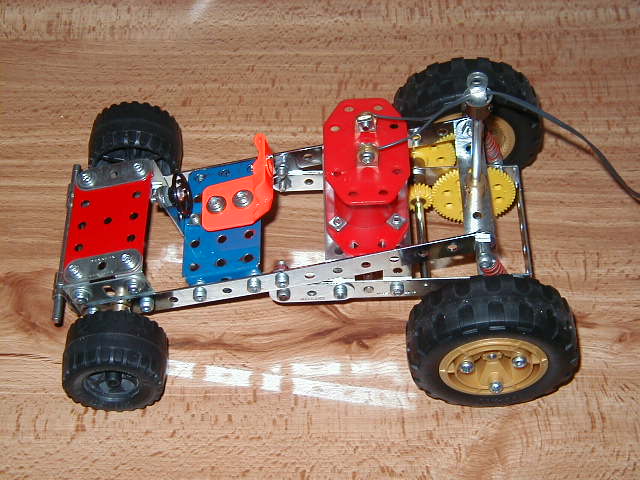
Brian’s version
Construction
The rear sub frame is a pair of 4½” strips and are fixed together by a pair of 2½” x 1” double angle strips placed three and five holes from one end. The front DA bolts also hold a 1½” x 1” corner bracket so one hole is free pointing up. The rear ends of the two strips are connected by a 2½” x ½” DA also holding a pair of spring shock absorbers by pivot bolts (part 147D) so are free to move.
Bolted to the pair of DA’s mentioned above is a French Red 3–6V M0 motor.
An 11 toothed cast pinion is fixed boss outwards on the motor armature shaft. Engaging with this pinion is a 50 tooth contrate gear, plastic preferably, to reduce weight, fixed on a 3” rod located by a collar and a 19 tooth pinion. The last gear meshes with a 57 tooth plastic gear on a 3” rod. The rod is located by a further 19 tooth plastic pinion. The final shaft is a 5½” rod, located by collars, with a further 57 tooth plastic gear engaged with the previous 19 tooth gear.
The rear wheels and tyres come from the recent 50 model set, and are fixed to the ends of the 5½” rod by means of a pair of 6 hole bush wheels, one each side, fixed to the holes in the wheels by 1” bolts and washers inside.
The other sub-frame is a pair of 7½” strips, bolted together by a 2½” x ½” DA across hole 1 at the rear, by a further pair of pivot bolts (part 147D) and the tops of the spring shock absorbers. The lower sub-frame is secured to these strips by the corner brackets single hole and should coincide with hole 8 of the strips. They are connected by 3/8” bolts and a pair of self-locking nuts, adjusted for free movement.
The lower ends of these strips are bolted together by a 2½” x ½” DA and two 1½” flat girders, one each side, forming a bonnet. These can be joined by a 2½” x 1½” flexible plate secured by four ½” x ½” angle brackets, the plate is edged by two 1½” strips.
A drivers seat mounting is a 2½” x 1½” flanged plate bolted between the strips using two washers per 3/8” bolt each side as spacing. On the top of the flanged plate is the drivers seat, using the seat from the 50 model set, bolted to the flanged plate by two ¾” bolts and an orange plastic spacer on each bolt.
The steering wheel, a Meccano Multikit part, is fixed to a 1½” x ½” angle bracket by a ½” bolt and nuts, secured in the central front hole of the flanged plate.
A front bumper bar is two right angle rod connectors with a 3½” rod fixed in the front holes of the 2½” x ½” DA of the sub-frame.
Lastly the front wheels — a 4” rod retained by collars, bearing each end wheels of choice, 1” pulleys and tyres or French road wheels or Liverpool 3 part road wheels. A device to prevent the motor wheels fouling the rear wheels is a rod socket secured to the rear DA with a 2½” road and an end bearing.
It is important to use a rubber band for the drive and not a Meccano drive band.