Leonardo Da Vinci’s Self-Powered Cart
Written by Alan Wenbourne in October 2021
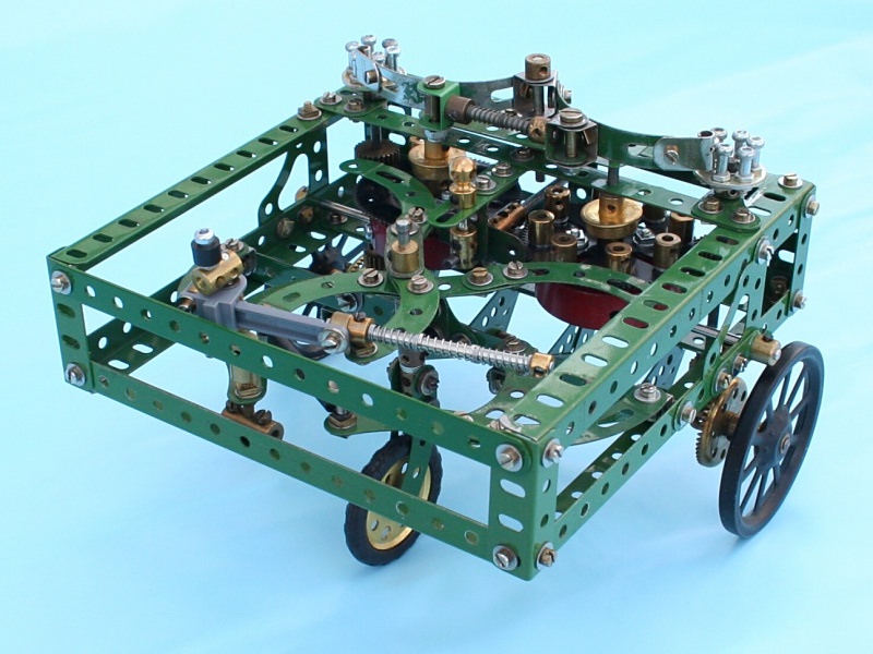
Figure 1 Initial Meccano model of Da Vinci’s self-powered cart
Background
In June 2016 I was asked to give a presentation and demonstration of Meccano to a class of children at Charlton Church of England Primary School in Dover, who were looking for inspiration for an in-class construction project.
As classroom space was limited I used my M4 High-Speed Tractor as the physical demonstrator and showed a 50+ PowerPoint slide presentation to cover the origins of Meccano, typical models from simple to more complex, and to indicate the range and diversity of subject matter possible in Meccano modelling. This was very well received by an attentive and interested class.
An outcome of this event was that I was invited to help supervise a group of the class on a visit to Dover Transport Museum. After recovering from the fact that I had never heard of this venue, on researching it I was amazed to discover the range of vehicles and memorabilia on display there!
On the day of the visit, whilst the children were being mustered and told how to behave during the visit, I had time for a preview of the museum. To my further amazement, in the foyer was displayed a large replica of Da Vinci’s self-powered chariot (figure 2). The vehicle is about 2m square, and is constructed in wood of quite massive proportions. One of the museum staff proved to be conversant with its working and gave me a credible explanation of how it was powered by the leaf springs connected to capstans driving the wheels. He had seen it operate on only one occasion when it travelled about 20 feet under its own power.
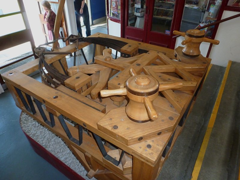
Figure 2 An interpretation of Da Vinci’s self-powered cart in Dover Transport Museum
I believe the wooden version on display had been produced by a university group some years ago, who claimed it to be their interpretation of Da Vinci’s famous sketch. It had been discovered in one of many buildings previously owned by the Ministry of Defence which was now used by the museum.
All this was a complete revelation to me as, over the years, I had studied Da Vinci’s sketch (figure 3) on several occasions, in the hope of reproducing it in Meccano one day, only to give up in despair of deciphering its working from the drawings, an outcome that many before me had also suffered apparently.
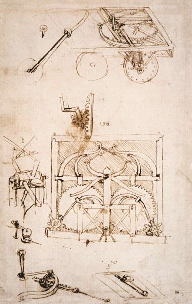
Figure 3 Da Vinci’s sketch, circa 1478
Further Research
The internet revealed some interesting results — over the centuries, many scholars have puzzled over Da Vinci’s sketch, most of whom assumed that the motive power was provided by leaf springs. This theory was questioned in 1975 by Carlo Pedretti (see reference 1) who proposed that the springs shown in Da Vinci’s sketch were not part of the drive system.
In 1996, Mark Rosheim wrote in a book that he thought that the ‘car’s engines’ were coil springs located in tambours (drums) on the underside of the cart. This led to Professor Paulo Galluzzi, director of the Museo Galileo (formerly the Institute and Museum of the History of Science) in Florence, Italy, commissioning a 3D CAD digital modelling project in 2004 (see reference 2). Videos of the actual and digital cart provide an excellent insight to the machine. The project realised full-size and one-third scale models of the cart, the latter being demonstrated in Florence in April 2004 (figure 4).
The museum referred to the machine as ‘Leonardo’s automobile’, implying it was the first car.
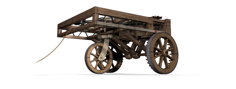
Figure 4 Working model of Da Vinci’s self-propelled cart — note the divided axle!
The Brake
As indicated in Da Vinci’s sketch, the machine is equipped with a brake that jambs between the tambour gears. This can be released by a rope allowing the machine to be set in motion by an operator hiding out of sight, thereby adding to the mystique.
Escapements
At the top of each vertical drive shaft driven by the tambour gears are rimless spoked wheels into which light leaf springs engage to perform a speed regulating function.
Programmable Steering
It transpires that the leaf springs, originally thought to provide traction, were part of the steering system. The gears above each tambour are fitted with a variable number of cams which operate arms, the opposite ends of which are attached to the aforementioned leaf springs. One of these arms is secured to the smaller wheel vertical shaft, thereby turning (steering) the wheel in response to the cam action.
The system means that the machine can only steer in one direction, unless the cams are rearranged.
The number of cams employed allows one or several steering actions per revolution of the large gears to which they are fixed, hence the term ‘programmable steering’.
Tension adjustment of the arm activating the steer motion is by a rack and pinion arrangement — this has led to a proposal that Da Vinci invented the rack and pinion steering mechanism.
A Question
After much study and repeated viewing of videos and other references on the subject, I was still unsure as to how these models actually worked. My dilemma was working out how the machine could steer, when the two gears above the tambours are meshed together. This arrangement means that both driving wheels are directly geared together, thereby not allowing any differential rotation. So there would be no point in the divided axle arrangement that Da Vinci’s sketch showed so clearly, and was adopted by Prof. Galluzzi in his model (figure 5). My mental analysis and initial Meccano model confirmed that the machine would not steer effectively without the wheel(s) skidding!
Did Da Vinci overlook this situation, misleading all the subsequent students and model makers? Or have I missed a point?
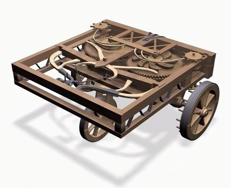
Figure 5 The 3D CAD model showing the meshing tambour gears and steering mechanism of Prof. Galluzzi’s project
The Meccano Model
Notwithstanding the question above, figures1 and 6 show my interpretation of Da Vinci’s machine in which the tambour gears do not mesh. Figure 6 is an overhead view of the deck with the Da Vinci machine features annotated and as interpreted in the model.
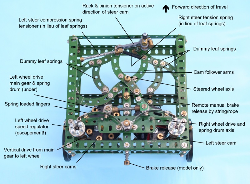
Figure 6 Features of the Da Vinci self-propelling cart as developed in model form
The obvious next issue was reproducing the clockwork mechanism. It could be imitated by using two Meccano clockwork motors; however, I wanted to copy Da Vinci’s intent, initially at least.
So a search for suitable clock springs that might fit into a Boiler End was made, without any success, until I consulted a horologist friend who referred me to Meadows & Passmore’s website which lists a large range of clock springs. The first hole end spring I ordered (13mm wide x 0.4mm thick x 50mm diameter) proved to be far too powerful to contain within a Boiler End without distortion. The second (10mm x 0.28mm x 28mm) proved easier to handle and I managed to capture the inner end via its hole, onto a Key Bolt with the tip ground off, fitted into a Coupling. The outer end was similarly attached to a shortened Bolt passing through the Boiler End flange.
With the one wheel driven by this spring the cart travelled about two feet! This proved the feasibility of the system, but obviously much more development was required in reducing friction and optimising the spring properties.
The Boiled Ends were attached to 95-tooth Gears which drive 25-tooth Pinions to each Spoked Wheel via 19-tooth Pinions and 50-tooth Contrate Gears. The cams for the ‘programmable steering’ are Threaded Bosses. As it is difficult to replicate the leaf springs of the steering and escapement mechanisms, I improvised using Tension and Compression Springs. The third steered wheel is a 1½” Pulley without Boss. The steering arm rack and pinion adjustment is by plastic parts.
The brake is a Trunnion, the flange of which engages with the 95-tooth gear teeth. This is spring-loaded in engagement to act as a ratchet when winding the springs. It is released by pressing the collar at the rear of the cart; disengagement is maintained by a toggle arrangement.
I was always sceptical of Da Vinci’s ‘escapement’ (speed regulator) and the first method I adopted to replicate it was not very effective. The interrupting action of the ‘flipper’ wastes power as the spring unwinds. With the minimal speed regulation control, it was necessary to fit tyres in the form of ‘Meccano’ elastic wrist bands to the driving wheels in order to prevent instantaneous wheel spin on release of the brake. The performance was short lived in time and distance and the use of compression and tension springs seriously limited the power to the wheels. A much lower rate system is required to minimize the power loss; maybe elastic bands would be better?
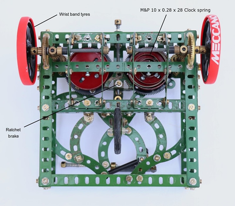
Figure 7 Underside view showing one spring installation and other detail
Further Development
A centrifugal governor could be more efficient, so a small governor design is in development which will fit into a 1–1/8” Flanged Wheel. The design precludes the use of friction elements due to its small size, so it relies on the centrifugal force between Collars and the internal cylindrical surface of the wheel flange.
As Meadows & Passmore’s available spring stock was limited, I searched elsewhere and found HS Walsh and Sons, who listed a more useful range of sizes for my application. Some of the problems of dealing with and selecting clock springs are difficulty in attaching the ends of the spring to the barrel and hub (this depends on the hole size in the spring ends) and separating the coils in order to make the connections when the spring is coiled! It can be very dangerous if the spring constraint is lost and it is allowed to freely uncoil — an aggressive jack-in-a-box! Presumably clock makers have developed techniques for handling this situation.
A HS Walsh and Sons 11mm x 0.3mm x 30mm spring has been earmarked for further experimentation.
See more photos of this model.
References
- Hooper, John. “Leonardo’s car brought to life.” The Guardian, 24 April 2004, www.theguardian.com/world/2004/apr/24/italy.arts. Accessed 15 October 2021.
- “Self-Propelling Cart.” Leonardo3 Museum, www.leonardo3.net/en/l3-works/machines/1441-self-propelling-cart.html. Accessed 15 October 2021.