M4 High-Speed Tractor
Written by Alan Wenbourne in May 2021
Background
For several years my model ‘wish list’ has included a crawler-tracked vehicle with a Gleasman-type double differential drive/steer transmission system, as shown in figure 1 (Gleasman did not invent the double differential, but he certainly exploited the principle in his patents). The original mechanism was developed and first built in France in 1921 (see reference № 10 in the bibliography).
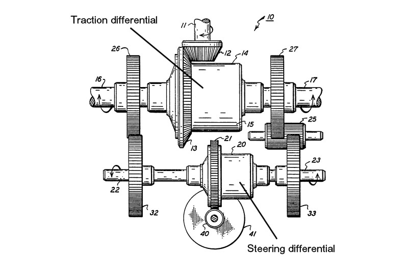
Figure 1 Gleasman-type double differential drive/steer transmission system, US patent № 4895052
My objective is to explore the controllability of the system in model form. The key to its success is in providing variable speed drive to the steering differential for infinite control of turn radius. Some systems used a stepped gear drive, which gave a fixed radius of turn for each step. Using a variable speed electric motor drive to the steering differential lends itself well to Meccano applications.
My model would need to be as small as practicable to enable using the Meccano Caterpillar track, as I did not wish to get into built-up track links and their associated mass, inertia and frictional losses. I am not interested in military tanks, so some alternative kind of tracked vehicle would the subject for modelling, preferably one capable of better performance than your average tank.
Research led me to consider the American (Allis-Chalmers) M4 HST (High Speed Tractor) (17’–2” long; 35mph), shown below in plastic kit model form, or the Morooka tracked dump truck perhaps.
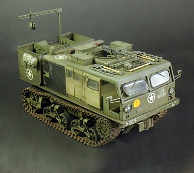
M4 HST plastic kit model built by Dung Lam Quoc
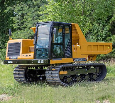
Morooka dump truck
Model Reasoning
The double differential system has received much discussion and modelling in Meccano publications. A review of those that I have seen shows the drive integrated into the hull of the vehicle with longitudinal motor axes driving the differentials through worm gearing.
I had the idea of making a modular double differential unit, as small and compact as possible, that could be adapted to various types of crawler vehicle — that way there is no need to decide on the type or scale of vehicle initially, and it could be determined later by the size of the drive/steer module.
My requirements are:
- That the model be capable of relatively high speed, in the range of 4–6mph, subject to the limitations of Meccano Caterpillar track and the practicality of installing sufficient torque and power.
- That it should be able to execute ‘on the spot’ turns at a reasonable rate — probably the biggest demand on power?
- That it should be radio-controlled with two electronic speed controllers, running off 7.2V DC NiMh battery power.
- The hull and the body could be separate modules allowing easy removal of the body if its weight were too much for the transmission system.
Performance Analysis
Initial calculations to estimate the required drive motor speed started with a nominal ground speed of 4mph. Using the formula: RPM = 168 x MPH / RR, where RR is the wheel rolling radius in inches, and estimating the pitch radius of the 10-toothed Meccano track sprocket at 5/16”, the sprocket speed calculates to 1,200rpm.
Motor Selection
In order to limit the speed of any Meccano gearing, consideration was given to using a geared motor from the MFA/Como Drills range and others, but the speed requirement proved this to be impractical if the drive differential was to incorporate a 57-tooth or 60-tooth gear as its crown wheel.
Speed also ruled out worm gearing to the drive differential, as the worm speed would have to be 68,400 rpm to get the required sprocket speed with a 57-tooth geared differential! This led to the conclusion that the motor should be parallel to the drive differential, with extra stage reduction(s) as necessary.
If a 60-tooth/15-tooth gear pair drove a spur gear differential, the 15-tooth pinion speed would be 4,800rpm. A further 1” spacing to a motor axis of 4:1 ratio indicates a motor speed of 19,200rpm!
I experimented with Mabuchi 540 frame size R/C and RS 550 motors because their ⅛” diameter shaft is easily sleeved up to 5/32” diameter and the mounting hole centres are 25mm, but the rotational speed of these motors was too low to incorporate a reasonable primary reduction stage.
By coincidence I have an Ansmann Racing, Clash 28, 540 R/C motor, which checked out at 19,200rpm off load. But we know that running Meccano gears at these speeds produces scary noise and vibration harshness! A primary speed reduction of 4:1 using a rubber band drive, and reinforcing some of the shaft journals, proved to be surprisingly acceptable driving a spur gear differential off load.
Steering Differential and Motor
With the drive motor crowding the differentials, and not knowing the speed requirements for steering, it was convenient to make the steering differential the conventional contrate type with right-angled input drive. An MO motor was fitted for this purpose in the hope that it would survive running at 7.2V, although this only occurs at the maximum rate of steer.
If the steering differential can be back-driven, differences in track friction and terrain etc. will allow unwanted ‘torque steer’ in operation via the traction differential, so the steering differential is usually worm-driven so that the vehicle will only steer on demand.
The Drive/Steer Module
The frame of the module is a 5½” x 2½” upturned Flanged Plate with 3” x 1½” Flat Plate side-plates through which the differential half shafts are journalled. The differentials and gear trains are shown in the overhead view of the module in figure 2.
Much time was spent mounting the motors and modifying the differential positions until a suitable arrangement materialised. The output shafts from the drive differential are long enough to attach track sprockets directly.
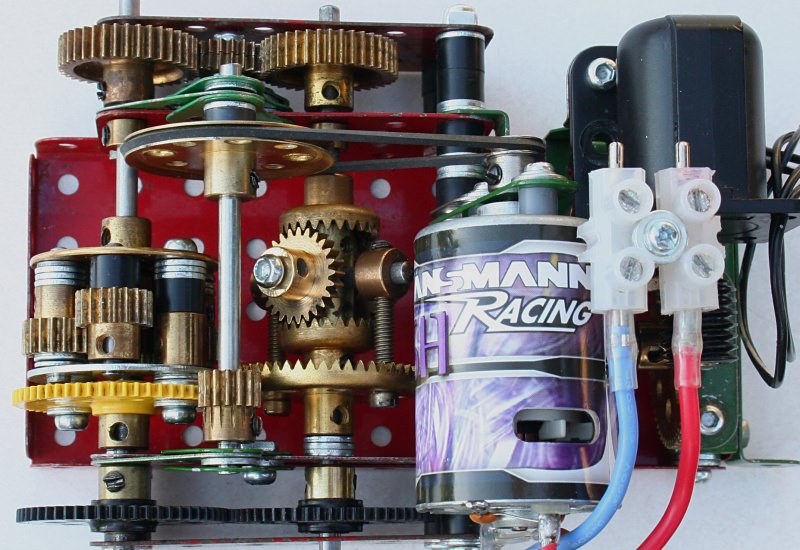
Figure 2 The prototype transmission module using an MO motor for steering function
Figures 3 and 4 are further views of the complete module.
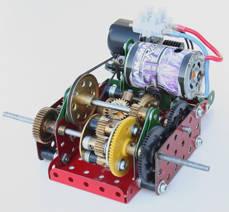
Figure 3 Prototype transmission module
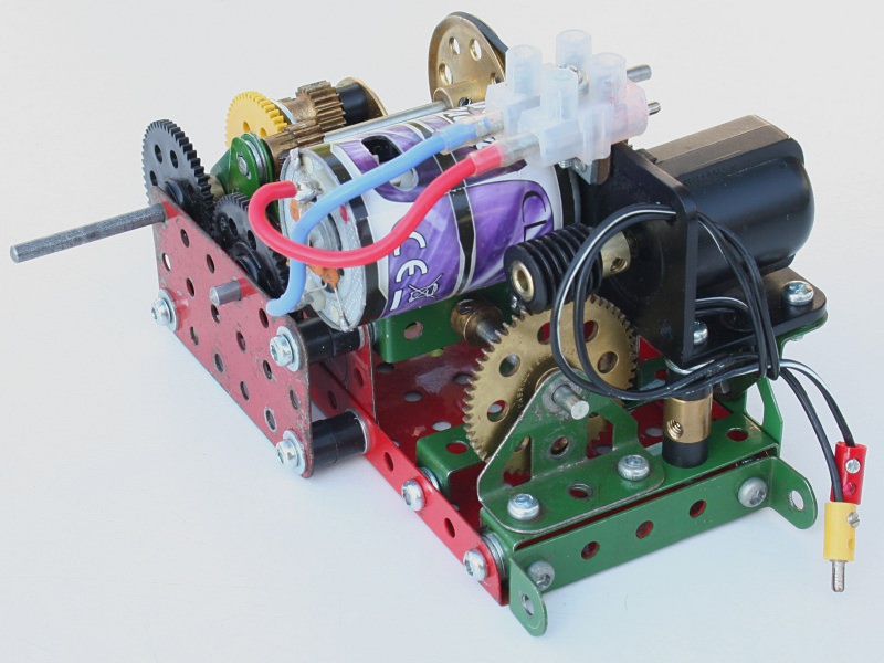
Figure 4 Prototype transmission module
Prototype Testing
To check the performance of the system, a pair of tracks were fitted to the module as shown in figure 5. The drive and steer functions were tested separately, there not being any radio control at this stage.
In drive mode, the module showed a good turn of speed, equivalent to brisk walking pace. In steer mode, the module turned on the spot at an adequate rate, and to my surprise, the tracks stayed on.
These tests were repeated outdoors, and for the record, the following statistics were recorded:
- Speed: 20ft in 3.05s = 6.56ft/s = 4.47mph.
- Steer (slew rate): 360° in 7.8s.
- Battery voltage: 7.34V
- Weight: 1.1kg (excluding battery)
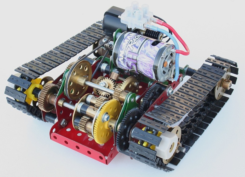
Figure 5 Prototype tracked transmission module with MO steering motor
Model Format
The double differential module may not suit some vehicle configurations with the motor above the differentials, but in others it could free up load space. However, by this time, a decision had been made to base the model on the M4 HST, shown below, as it had more attractive features to me and it was classed as ‘high speed’!
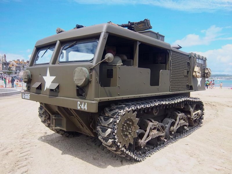
US Military version M4 HST
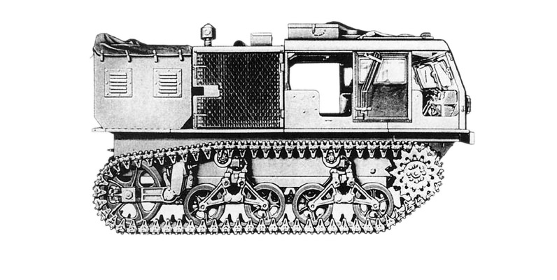
Figure 6 Side elevation drawing of M4 HST useful for scaling
Design and Development of the Hull
This progressed by extending the differential unit frame to scale of 1:15, based on the width over the tracks. Track rollers, rear tensioning wheels and suspension systems were added and the running performance checked at various stages to confirm that the extra weight could be tolerated by the plastic track and rubber band drive. This required some re-modelling to enable an increase in rubber band tension and the importance of track tension realised. Actually, there should be no ‘tension’ as this increases friction and rolling resistance considerably. The right amount of ‘slack’ is what is required.
Then the steering performance was tested and found to be virtually non-existent on the smoothest surfaces! So the steering motor was changed for a Faulhaber 12V geared motor. This proved to work, although somewhat slower that I would have liked.
The front, rear, sides and top surface features of the hull were modelled, as shown in figure 7, with complete disregard to the increased weight of 2.4kg.
This proved to be limit of the traction system as it would drive in reverse but really struggled in forward, the motor would stall or the motor pulley would slip the drive band.
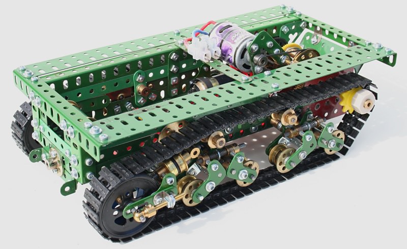
Figure 7 Completed hull with transmission, tracks, rollers, suspension and guide wheels
Study of the front driven sprocket configuration explains the problem, since in reverse; the part of the track in tension is the short span between the drive sprocket and the front track roller, but in forward, the section of track in tension is that embracing the top guide rollers, rear track tensioning wheels and the four lower track rollers! This obviously induces much more friction to motion.
To compound the disappointment, the steering system would not move the model in either sense — back to the drawing board!
Transmission Redesign
Dealing with the drive system first; running with the tracks off the floor and observing the track speed, convinced me that it is probably unreasonable to run a model of this size and mass at that speed (half the observed track velocity).
The original M4 had a top speed of 35mph, which if scaled to 1/15th (ignoring time) indicates a more realistic scale speed of 2.33 mph. So the aim would be to increase the torque and reduce the speed, which could be achieved by adding an extra 2:1 reduction stage to the gearing.
Once this was done the hull performed much better, making 1.97mph forward and 2.02mph reverse, with the motor under less strain than previously.
A further attempt at slewing with the Faulhaber motor produced smoke and a dead motor!
It was time to make an estimate of the required slew rate, and I considered that 360° in 10 seconds would be good. Also, it took 40 revolutions of the steering differential input to slew 360°. So a speed of 240rpm into the steering differential would be required.
An MFA/Como Drills 918D15112/1 geared motor (15:1 reduction) was fitted, directly driving the steering differential, the off-load speed of which should be 230rpm at 7.2V. This worked on very smooth surfaces with some lugging of the motor but at least it proved the theory.
A heavier duty MFA/Como Drills 940D271 geared motor (27:1 reduction) with planetary reduction gearbox was purchased, which should make 240rpm at 7.2V. A 15-tooth pinion was drilled out to Ø6mm to fit the output shaft and a 1½ x 1½ Flanged Plate modified to mount the geared motor. The unit was fitted to the hull and tested with very satisfactory results; the hull slewed through 360° in 10.65 seconds.
The radio control system was fitted, and consisted of a Mtronics Viper Marine 40 electronic speed controller (ESP) for traction control, a Viper Marine 15 ESP for steering control, Ansmann R5 receiver, a new compact NiMH 3,700mAh battery pack and Ansmann W5 2.4GHz digital transmitter.
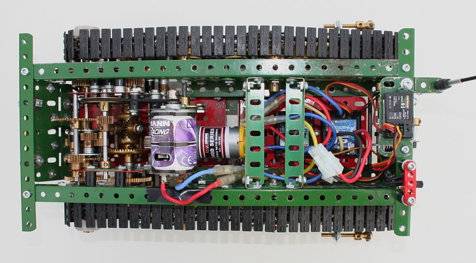
Figure 8 Overhead view of the hull showing transmission, motors and radio control gear
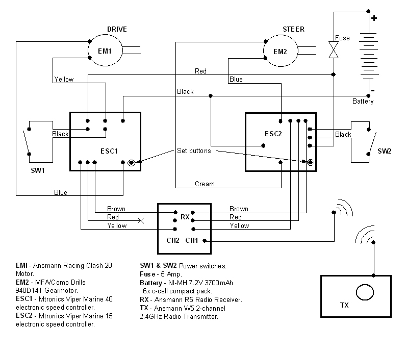
Figure 9 Radio control circuit
Under R/C control the hull performed very well, making turns at low speed and on-the-spot slewing, proving the controllability of the system. Because of the relatively fast top speed, a higher speed steering motor would provide better steering control at full speed.
Sourcing an alternative steering geared motor was proving to be difficult — MFA/Como Drills listed a 940D geared motor with 14:1 planetary gearbox, available for a minimum order of 100 units and a six-week lead-time! This combination would give twice the steering rate at half the torque output of the 940D271 unit, which appears ideal. A chance phone call to MFA/Como Drills revealed that they had the 14:1 version in stock (because some obliging customer had previously ordered a large quantity) and the price was only £5 more than the 27:1 version! I couldn’t order one fast enough!
In the meantime the body was modelled and arranged so that it located and connected to the hull by threaded pins at each corner acting as dowels, enabling easy access to the hull for battery fitting and removal and servicing etc.
The 940D141 duly arrived and was fitted. Tests on a tiled floor without the body were very encouraging, allowing steering control at speed (within the limited floor space) and on-the-spot slewing at a good rate. However, with the body fitted, one steering differential contrate side gear started jumping teeth. Adding spacer washers between the contrate and gearbox sideplate overcame the tooth-jumping problem.
A second drive/steer module was constructed that would accommodate a contrate-driven spur gear-type differential, should that prove necessary. This design is a simplified arrangement using 2½” x 2½” sideplates and revised speed reduction stages (3:1 primary and 3:1 to drive differential). The meshing 57-tooth gears could be replaced with wider-faced versions from Stuart Borrill.
The model features a dummy anti-aircraft machine gun, a dummy winch, munitions crane and ammo storage compartment, towing attachments and US army decals. Track rollers and rear wheels are independently sprung and fitted with track slack adjusters. The rear track adjusting wheels are 2” pulleys fitted with ‘O’ rings to guide the tracks.
In 2021 the primary reduction was changed to a toothed pulley and belt system which proved totally reliable during manoeuvres and many laps of the circuit at the 2019 SELMEC Meccano Show.
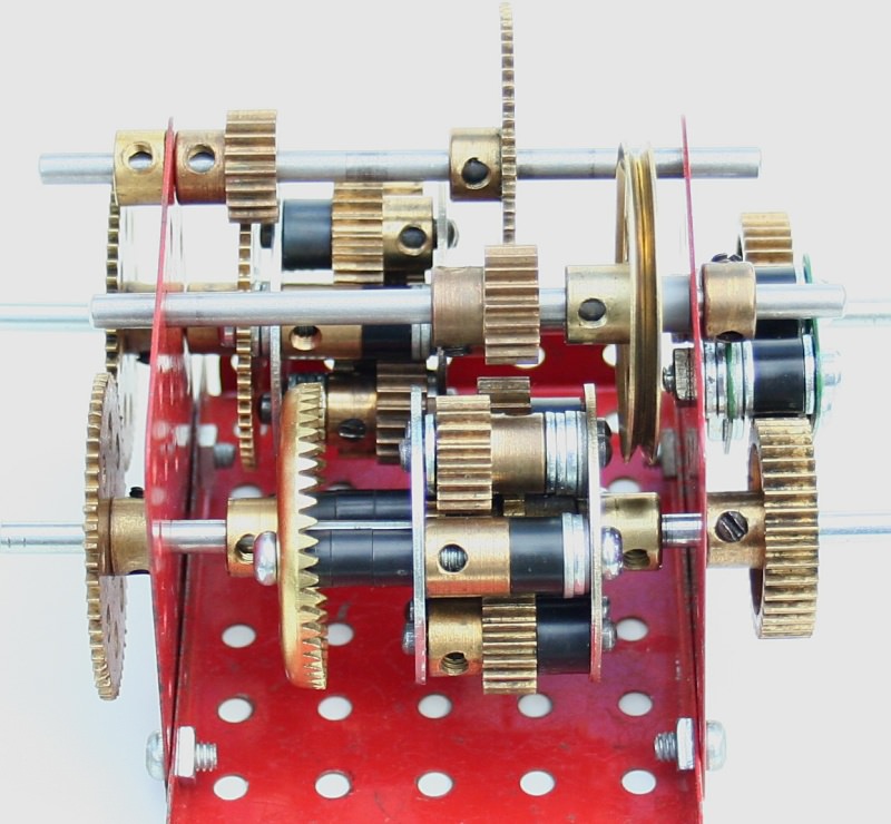
Figure 10 Alternative transmission with spur gear steering differential
Conclusions
The performance and controllability of the model exceeded my expectations, being capable of any radius of turn and rapid on-the-spot slewing. In its final form with body attached it makes 2mph maximum speed and a slew rate of 360° in 5s and reacts very much like a wheeled vehicle.
In the real world, crawler vehicles can only achieve this degree of steering control by utilising two independently variable speed drives. One expensive solution is a hydraulic motor drive to the steering differential, using a variable displacement pump or motor combinations and very sophisticated hydraulic control systems. The infinitely variable speed, radio-controlled electric motor drive is a perfect solution for models.
Three overall views of the model are shown below:
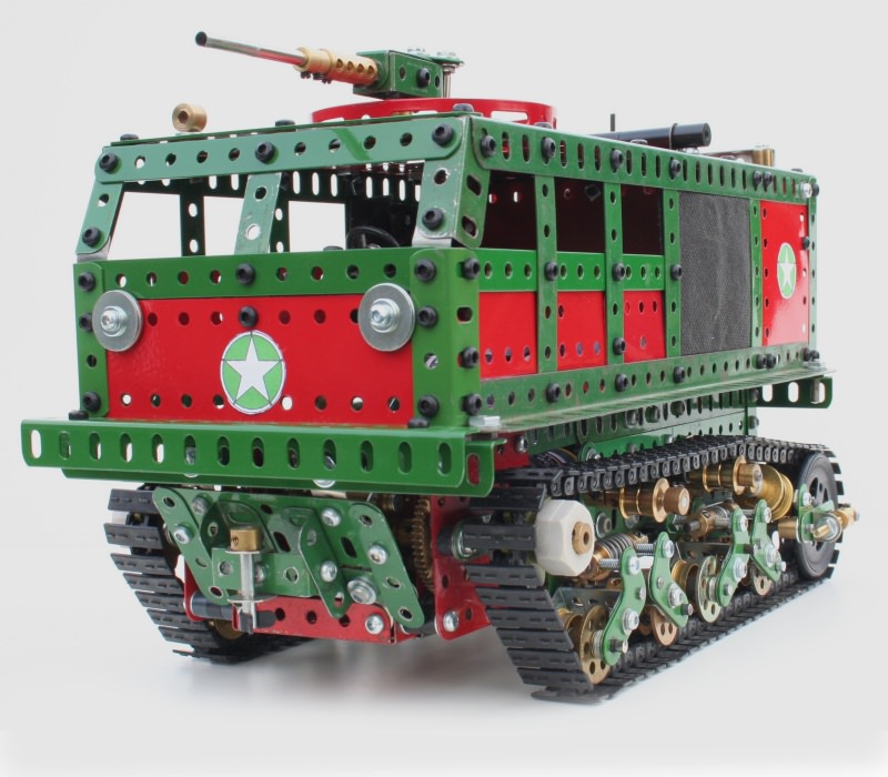
Front view
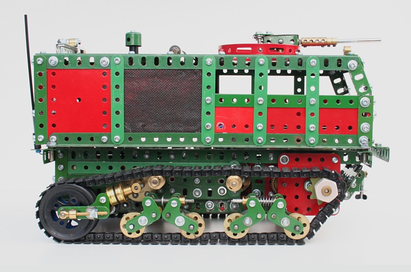
Side view
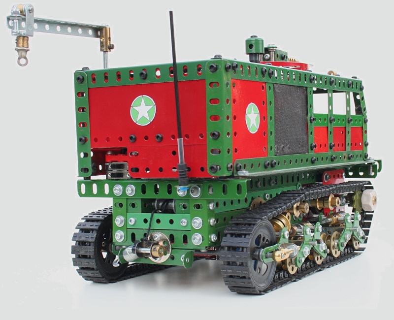
Rear view
See more photos of this model.
Bibliography
The following bibliography of authors, modellers and publications is provided in recognition of their assistance in my research:
- Edwards, Phillip. “Differentials, the theory and practice.” Constructor Quarterly, issue 1, September 1988.
- Cameron, Dr. Keith. “Gleasman’s All-Gear Track Steering.” Sheffield Meccano Guild Magazine, December 1986 / Constructor Quarterly, issue 2, December 1988 / Meccanoman’s Newsmag, issue 54, July 1989.
- Partridge, Alan. “Mistaken Claim?” (letters). Constructor Quarterly, issue 4, June 1989.
- Kind, Guy. “Gleasman tank transmission and a gear selector mechanism.” Constructor Quarterly, issue 28, June 1995.
- Gleasman, Vernon E. “Multi-axle vehicle steer drive system.” US Patent № 4895052, March 1988.
- Goddard, Peter. Meccano double differential layouts.
- Collins, Dave. Drive model shown at the North East London Meccano Club exhibition, 2012.
- Browne, Adrian. “Gleasman Steering.” International Meccanoman, issue 64, autumn 2011.
- Fire and Movement. RAC Tank Museum, 1975. Courtesy John McDonald.
- Ogorkiewicz, R. M. Design and Development of Fighting Vehicles. Macdonald (London), 1968.