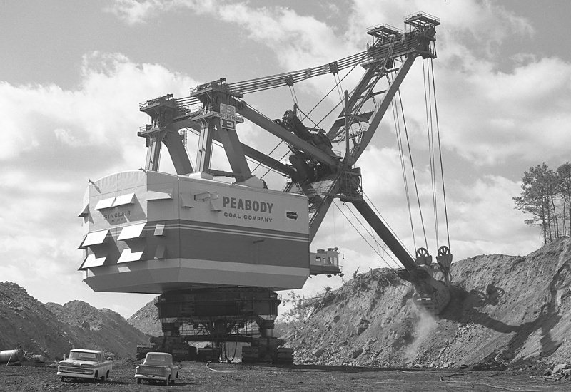
“Big Hog” Bucyrus Erie 3850 Giant Stripping Shovel
Written by Greg Clarke for our June 2010 Newsletter
Brief History
‘Big Hog’ at work
The 3850B nicknamed “Big Hog” was Bucyrus’s largest shovel type and when it was first commissioned in 1962 it was the heaviest land machine ever built. It weighed 9000 tons and had a bucket which could dig out 160 tons of rock in a single bite! It soon lost the heaviest accolade however to its sister machine in 1964 then ultimately to the mighty Captain shovel built by Marion in 1965 which exceeded 15,000 tons! These massive machines were used to remove overburden at surface coal mines in the Midwest and central parts of the United States. The hog was retired and buried in its own pit in 1984 when the mine was shutdown, and its sister machine went the same way in 1993.
The Model
I’ve been fascinated in large mining equipment since I picked up a book on the subject at a steam rally in the 80s, so it was natural that I would have a go at one in Meccano at some time. I read with much interest about Guys Captain shovel that won the Issigonis shield eight years ago so I didn’t want to copy it and needed to pick another machine. Big Hog was a natural choice as it used several quite different engineering features to the larger Marion built machine, and would present some interesting challenges.
Watch our video of this model
Crawler Sets
The machine is propelled by four sets of double crawler tracks mounted under replica cylinders at each corner of the lower works. Each one is built up using 5½” angle girders and flat girders with a 1½” square plate and wheel flange mounted on the top to take the weight of the machine. Each crawler would need to be independently driven with small but powerful motors. For this job I purchased four Swiss made 350:1 geared motors with 3mm drive shafts and sent them up to Stuart Borril to get special 19-tooth pinions and 1½” square plates pre-drilled for mounting. Each 19-tooth pinion meshes with a 57-tooth spur gear which then transmits the drive via small sprocket and chain down to the plastic caterpillar track sprockets. The plastic sprockets have been drilled to accept collars inside as the torque and model weight (17kg) would soon strip them out. At the opposite end of each crawler set there is a single HD compression spring to act as a tensioner and help prevent the tracks coming off the sprockets as they like to do. The crawlers attach to the lower works by 5” rods journalled through 3½” sleeves and 2½” cylinders which simulate the massive hydraulic cylinders used on the original.
Lower Works
This is the name given to the box like structure which the crawler sets and slewing support ring is mounted to. Again this had to be very beefy so I used 7½” and 5½” angle girders top and bottom of each side plate with four wheel cylinders to act as the top journals for the support cylinders. To support the slew gear there is a single 7½” circular strip bolted across the top of the angle girders. Upon this are eight threaded collars and four rod sockets. At one end I built a mock up of the giant electric cable reel complete with cable guide. At the other I made up a small junction box hidden behind a flexible plate on a hinge to make access easy when the top and bottom halves have to be separated for transport etc.
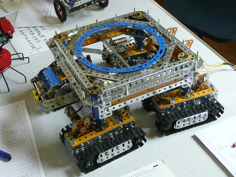
Lower works and crawler sets
Steering
The steering is performed by a 100:1 geared motor which drives a worm meshing to a 19-tooth pinion. This is attached to a special extended length rod socket threaded to 6mm which screws onto a threaded shaft. An identical rod socket is fitted to the opposite end and these both journal into a 62b double arm crank which provides a strong thrust bearing to counter the load when the shovel steers. A special M6 threaded coupling runs up and down the shaft to which is attached two sets of seven hole narrow strips sandwiched three thick. These again via couplings attach to 7” rods which act as the tie rods with swivel bearings at each end. Finally the swivel bearings with shafts mounted vertically pivot at the inner end of each crawler set. This all works quite smoothly and the despite the weight the motor runs effortlessly. The weakest part is occasionally the couplings slip on the 7” rod causing uneven steering angle and have to be re-aligned.
Upper Works
This is the name given to the machinery house and the support for the boom and A frame. It is constructed very simply from 12½” girders mounted onto a series of 5½” x 2½” hole plates attached to the 6” circular plate of the slew gear. I decided to build all of the slew gear to the upper works including the roller bearing assembly and a cage which supports the 3½” ring gear. To increase the teeth contact area a 3½” gear wheel is sandwiched to a 3½” gear ring. At first a single 19-tooth pinion was used for meshing to the main ring but it soon became obvious this would not be man enough so a major refit of the machinery deck was required. A PDU motor set at 6:1 to save the expensive gearbox uses a large belt drive to a 1½” pulley. This in turn drives through a friction clutch and various reduction gears. Finally drive is changed vertically via contrates to the two shafts which are attached to the 19-tooth slew drive gears. This all works fairly smoothly at a slewing rate of about 3 rpm. The clutch provides some protection if the machine is turned without using the motor. The crowd mechanism is driven by an MO motor and 19:1 reduction gearbox mounted in the vertical. This in turn using a 171 coupling and two shafts then performs three sets of reduction before the final chain drive. The drum is formed from two 6-hole flange wheels connected by 4” rods. One cord only performs all the crowd movement.
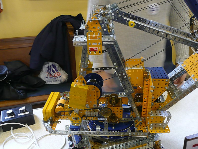
Upper works
A Frame and Hoist
The A frame is made from various angle and flat girders and features two maintenance decks complete with hand-railing. You will note from the photos several miscellaneous ½” and ¾" pulleys mounted to the top cross brace and each A frame between the maintenance decks. These pulleys don’t appear to be performing any function, but they match the prototype and after investigation I found out that they were used during the building of the machine to raise the 500 ton boom section using the shovels’ own hoist ropes. After the machine was complete all this redundant equipment was left in place. Two sets of angle girders are used as the main boom bracing which is attached to the top of the A frame and pins to four trunnions attached about a third of the way up the boom.
The hoist machinery was rebuilt at the same time as the slew gear as I was not happy with the original. The problem was that in order to duplicate the prototype’s twin rope arrangement for lifting the shovel’s stick and bucket, any unequal paying in or out of the rope drum would result in the cords going slack on one side and looking unsightly. Clearly a differential was required so that’s what I did. The hoist is driven by an MO motor gearbox combination after several spur gear reductions. Drive to the differential is via a chain drive arrangement. Tension adjustment for this drive is taken up via 96a 14-tooth sprocket which has come loose from its boss. This makes a perfect idler sprocket from an otherwise useless part!
Two sets of boiler ends and large flange wheels form the two hoist drums. The two cords for the hoist both start and end at the drum which is unusual but matches the prototype. There is no mechanical advantage in multi-reeveing with this design, so I can only assume the designers used the double breaking strength advantage of two cords. The arrangement is simple with each cord ran over the boom head 2” pulley, down to the dipper 2” pulley then passing each side of a 1” pulley that swings freely from the top of the boom head.
Boom
The boom is quite flat but very wide compared to crane-style booms. The lower part uses various yellow and zinc parts that appear almost solid in construction with the upper made up from a series of chevron style cross bracing. The boom head is suitably busy and the whole affair is adorned with maintenance platforms complete with hand railing. Four cords on each side run from the A frame to the boom head to act as upper boom support ropes, with two additional cords per side running vertically down to the mid-boom level. One visitor at SELMEC likened it to the rigging on a ship, but I have only modelled half of what is on the prototype!
Saddleblock
The saddleblock is the name given to the giant bearing assembly that supports the stick and allows it travel smoothly back and forth when the machine is digging. This motion is called ‘crowd’, the drive mechanism of which I covered earlier in this article. The saddle block frame is a simple box arrangement of angle girders pivoting on the centre to allow the whole assembly to pitch. As the stick is formed using a series of sleeves bolted together, a smooth bearing was required that also allowed the stick to ‘yaw’ slightly. This was a feature of all Bucyrus Erie rope crowd shovels as they soon discovered that when the shovel hit a hard rock face the side shock would be absorbed by the boom and pivot mechanism causing a lot of damage. To achieve this I came up with the idea of using 8½” tyres fitted to plastic collars to give a front and back four-point bearing surface. These run freely on 1½” rods journalled into 133a trunnions. The spring tension which allows the ‘yaw’ movement is created by two sets of two compression springs pushing the trunnions out to keep constant tension on the side of the stick. The arrangement worked first time and I was suitably pleased with the effect.
Stick and Dipper
As mentioned above, the stick is made from the longest sleeves that Dave Taylor can offer bolted together from the inside using strips to link them. At each end a set of white plastic 1” pulleys act as crowd pulleys. The stick was hollow on the prototype; 7’ in diameter, 3” thick, and 140’ long. It had to be reinforced with another 3” of steel soon after entry into service due to stress cracks. The dipper includes the bucket which is fixed to the stick and the hoist pulley assembly. At the time of writing this article I had not bothered to model the hinge mechanism of the bucket but I may do so later in the year. It’s construction is clear from the photo. The hoist pulley is formed of two 2” pulleys which are free to pivot in two planes independent of each other. This makes reeving of the cord interesting, especially with a differential always trying to take up the slack!
Conclusion
The model has taken about a year to complete with an estimated 200 hours. It has been enjoyable with several challenges overcome. I plan to keep it for the summer season of exhibitions before it becomes something else! For me the building is the pleasure and once complete I am itching to start the next one!
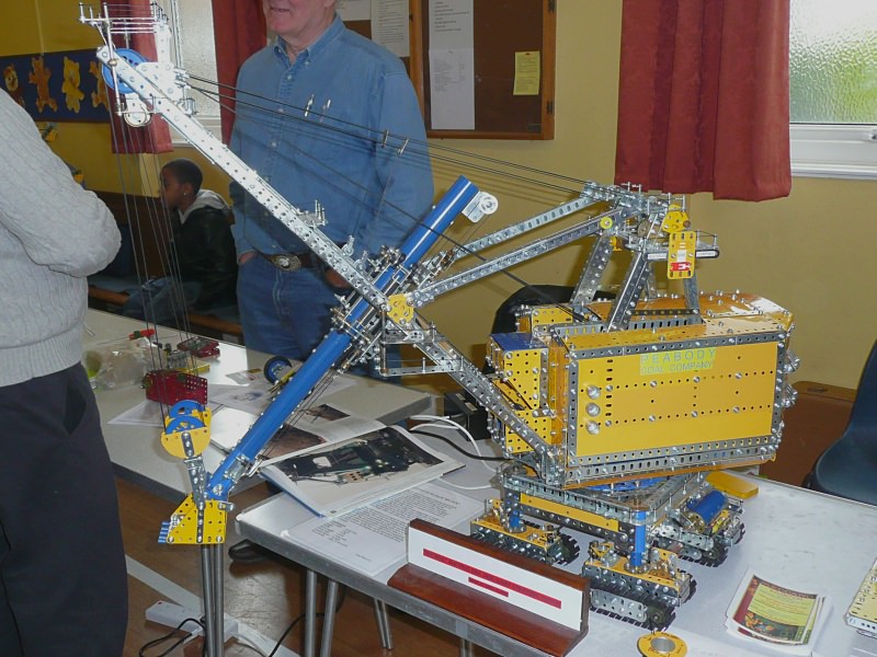
The Bucyrus Erie 3850 Giant Stripping Shovel model