Cletrac Controlled Differential Steering System
Written by Alan Wenbourne in February 2021
The double differential arrangement used in my M4 HST Military Munitions Tractor (described in Runnymede Meccano Guild Magazine issue 84 and also in Constructor Quarterly issue 105) proved exceedingly effective in controlling a relatively heavy track-laying model vehicle. The model performed very well at speeds up to 6.5ft/s and demonstrated good steering control — in fact as good as a wheeled vehicle when under radio control.
However, the system required two variable-speed drives to work effectively, and radio control via two separate electronic speed controllers. Not your typical Meccano components!
I decided to revisit this subject to see what alternatives there may be to the double differential system, and I began to wonder about modelling a simpler system such as the Cletrac drive, which uses a single differential with steering brakes. This is a controlled differential which overcomes the disadvantages of the skid-steer systems that waste energy. It does not directly brake either output shaft but proportions the drive to both, thereby facilitating a fixed radius of turn when one brake is fully applied dependent upon the ratio of the additional planetary gears. No power is wasted in applying the brake(s), so the system is regenerative.
Anecdote
In my adolescence I was nuts about anything on wheels or tracks and wanted to be a motor mechanic, but that idea failed at the youth employment interview stage (that’s another story). However, I owned a Dinky Supertoy Blaw Knox bulldozer which was the pride of my collection and there happened to be a Blaw Knox factory near my home in Rochester. On leaving school I managed to secure an apprenticeship with that company. However, it was not long before I realised that Blaw Knox did not make bulldozers! They merely made the blade assembly which was designed to fit a Cletrac tractor.
Background
The Cletrac system was patented by Rollin H. White, founder of the Cleveland Tractor Company, who pioneered the use of track-laying machines during the same time the C. L. Best Gas Traction Company and the Holt Manufacturing Company were perfecting their crawler tractors. The Best and Holt companies merged in 1925 to form the Caterpillar Tractor Company. White’s first tractor patent using controlled differential steering is shown in figures 1 to 4.
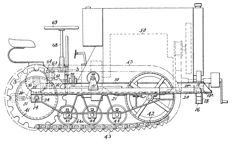
Figure 1 Side view of the Cletrac tractor in Rollin H. White’s patent
The tractor was steered via a steering wheel mounted on a vertical column, driving through a ‘V’ formation of gears to the screw jacks of the external contracting steering brakes. This ensured that both brakes could not be applied at the same time.
Figure 2 is a plan view showing the differential, steering and track layout. Figures 3 and 4 show sectional details of the differential, steering and brakes.
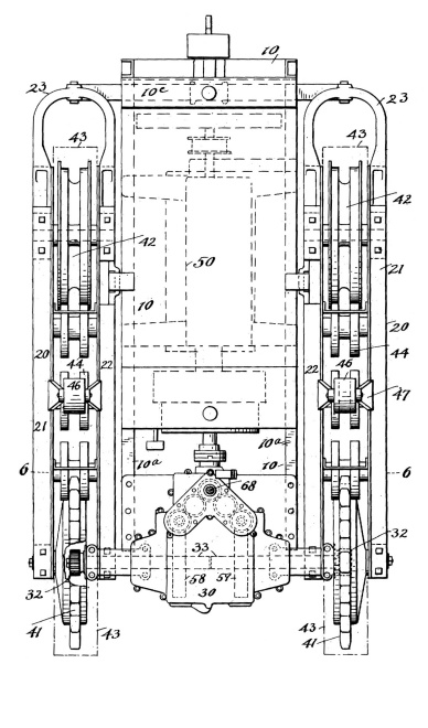
Figure 2 Plan view
The differential is a spur gear pinion design with an additional planetary set either side connected via their sun gears to the steering brakes, as shown in figure 3.
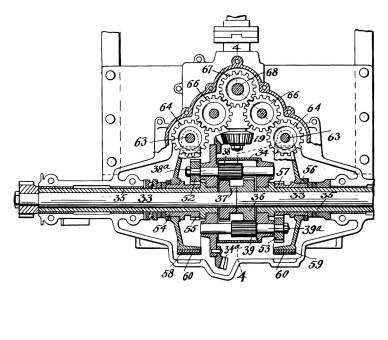
Figure 3 Sectional details
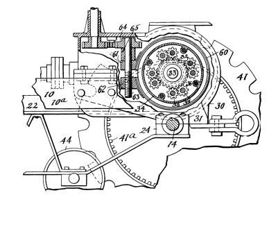
Figure 4 Sectional details
The first tractor to be equipped with Cletrac controlled differential steering was the model ‘R’ in 1916.
The controlled differential steering system was very successfully applied to all future Cleveland tractors and was used in many military vehicles, APVs and battle tanks internationally.

1918 ‘W’ Cletrac tractor with Weidley motor
Meccano Modelling
My initial conditions for modelling the Cletrac system were that it:
- should be as small as possible, so as to demonstrate manual steering control on a table top,
- be battery powered with a Meccano motor,
- not necessarily have external contracting brakes (too difficult to model in a limited space).
- use Meccano crawler track.
- follow the White patent proportions as far as possible,
- use standard Meccano parts if possible.
The Model
An initial attempt at modelling a very short spur gear differential, based mostly on narrow faced pinions, failed on the old problem of there being no centre bearing for the half shafts, so extra length crept in by having to use one standard 19-tooth pinion sun gear and two Bush Wheels for the cage, thereby providing better journaling for the half shafts. The additional 13-tooth planetary Pinions (G1 = 25-tooth and H1 = 13-tooth), had to be located in Socket Couplings to attach brake drums, which were initially Wheel Flanges on Bush Wheels. This added rather more width than I had anticipated.
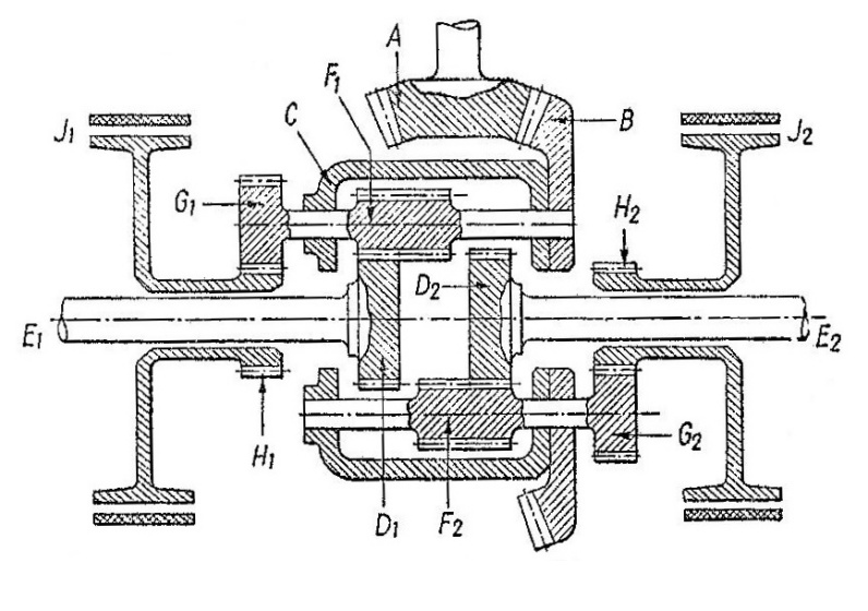
Figure 5 Diagram of the Cletrac differential (Figure courtesy of Dr. H. E. Merritt)
So the Socket Couplings were substituted for non-standard versions to save width and the Wheel Flanges substituted for Face Plates in the hope that I could invent some kind of disc brake mechanism to avoid the need for large external contracting brakes.
The ‘breadboard’ arrangement shown in the photo below developed, with a PDU motor, a slip clutch to protect the motor, spur pinion differential, planetary gearing, Face Plates as brake discs, and newly invented brake calipers.
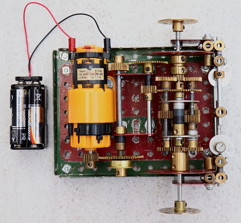
The mechanism and motor
The brake calipers are pairs of Couplings, one fixed, the other free to slide. The fixed Coupling acts as one brake pad and carries a second coupling for mounting. The free Coupling has attached a Threaded Boss as the other pad. The free Coupling is driven against the other by a Cam, thus clamping the Face Plate. The free coupling is disengaged by a shortened Compression Spring between the Couplings. The Face Plates are allowed axial float to ensure free disengagement.
When the left-hand brake is fully applied, the planetary gearing sets the left-hand track speed at 0.479 (13/25) times the rotational speed of the differential carrier; the right-hand track speed is 1.923 (25/13) times the carrier speed. Thus, the difference in half shaft speeds is 3.1739:1. This, together with the vehicle velocity and geometry dictates the minimum radius of turn.
The PDU was set to its 12:1 ratio for initial testing, running off four AA batteries and the clutch adjusted to protect against stall conditions. Initial testing with manual brake operation proved promising.
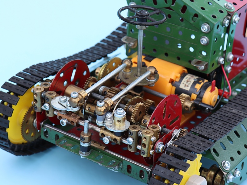
The mechanism mounted in the model
The breadboard frame was extended at the front and drop gearing added at the rear to mount 20-tooth plastic sprockets, and ¾” Flanged Wheels completed the running gear.
The steering Cam leverage was extended slightly by adding slotted Narrow Fishplates and to provide a fixing hole for the brake linkage. Then the Steering Wheel and control Rods were added.
Despite proportions of the drivetrain, I decided to model an out-of-scale engine housing and footplate in keeping with the Cletrac ‘H’ tractor.
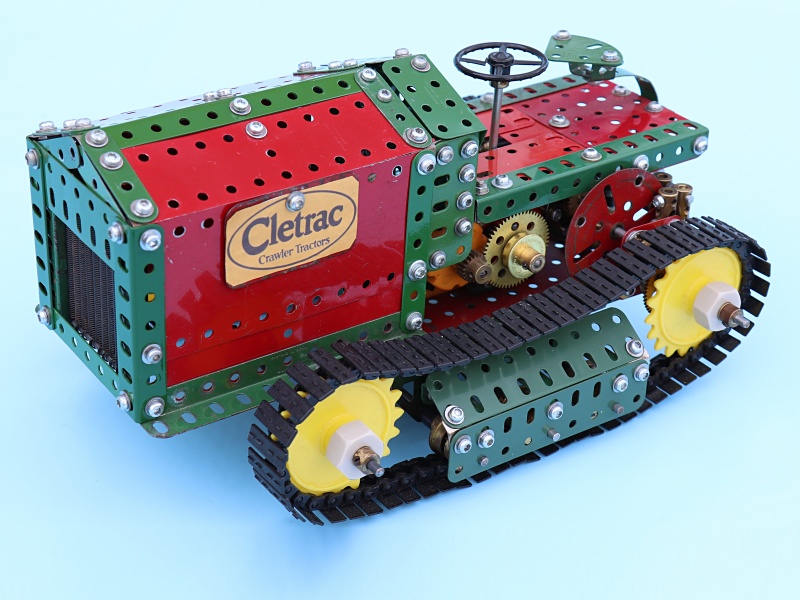
The completed model