Triple Differential Drive Steer Transmission
Written by Alan Wenbourne in March 2022
Background
This version of the triple differential, shown in figure 1 (reference 1), is known as the Merritt-Brown TN.12 transmission, and it is used in the Churchill, Centaur, Cromwell and Comet battle tanks. Professor Merritt, an expert gear and gearbox designer, worked with the David-Brown company.
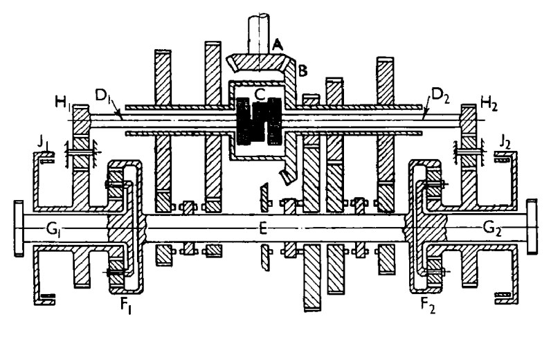
Figure 1 The triple differential
The Merritt-Brown transmission incorporated a four-speed and reverse crash change gearbox between two output epicyclic drive units. Later Merritt-Wilson units used a Wilson type epicyclic gearbox as used in the Chieftain tank.
It is convenient to quote Dr. Merritt’s succinct explanation from his paper (reference 1):
The input shaft A drives a primary Shaft B of hollow construction. Externally, shaft B is geared to a secondary shaft E by alternative pairs of change-speed gears and shaft E also carries and drives the annulus gears F1 and F2 of the output epicyclic trains. Within the primary shaft is a differential C of the spur gear type which drives the half shafts D1 and D2, and the half shafts drive the sun gears of the output epicyclics through the steering trains, each of which includes an intermediate gear.
The output shaft G1 and G2 are connected to the planet carriers of the epicyclics whilst the respective sun gear shafts carry steering brakes J1 and J2.
In forward straight line motion the output shafts move at equal speeds made up of two components combined by the epicyclics. They are a component derived through the annulus gear and proportional to the speed of the secondary shaft, acting in a forward or positive direction, and a component derived through the sun gear and proportional to the speed of the primary shaft — this component is negative because of the presence of the intermediate gear in the steering train. The overall gear ratios are therefore modified by the presence of the negative component and have a wider spread than the ratio of the change-gear pairs themselves; and if the secondary shaft is locked, the negative component acts alone to give a reverse speed.
In order to steer, one steering brake, say J2 is applied. If the drum J2 is brought to rest, the speed of the primary shaft remaining unchanged, the negative component of speed received by G2 from its sun gear vanishes, and G2 speeds up by that amount. Owing to the action of the differential C, the sun gear associated with output shaft G1 rotates at twice its previous speed, and doubles the negative component applied to G1 which in consequence slows down by the same amount that G2 speeds up.
The angular velocity of turn and the steering power are proportional only to the speed of the primary shaft, and the radius of turn increases in the higher gears.
When reverse gear is engaged, the effect of steering is to lock one track and the vehicle executes a skid turn. It is curious to note that if the change-speed gearbox is in neutral, the steering brake drums continue to rotate with the primary shaft, and if a steering brake is operated the effect is to apply equal and opposite torques to the output shafts. The tank then makes a pivot turn.
The paper makes no reference to whether the steering brakes may be modulated to control the turn radius up to the minimum values that are generated in each gear. Whilst such brake slip would waste energy, it would enable small directional corrections to keep the tank running more or less straight.
The Model
The main challenge to modelling this transmission is incorporating a transverse gearbox between the output epicyclic units, which leads to a rather wide assembly.
The model described here is based on the diagram in figure 2, taken from a Haynes manual (reference 2).
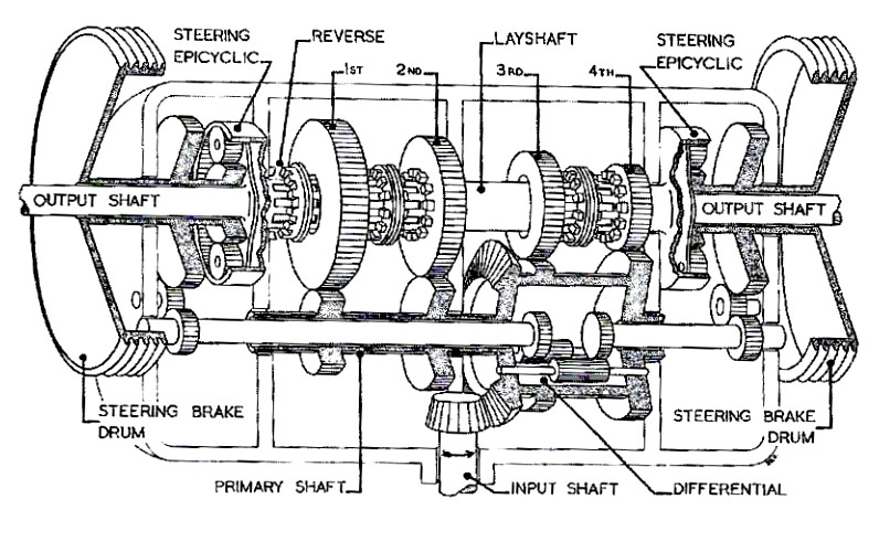
Figure 2 Churchill tank transmission diagram
The first attempt used a bevel pinion and gear drive to a spur pinion differential and three-speed, speed increasing gearbox. It was not possible to include the fourth gear because of the difficulty in connecting four change speed gears to the differential cage on the primary shaft. Also, reverse required a separate gear train. The idea provided the intended directions of rotation but was abandoned in favour of an extra shaft axis, to form the input/output of a more conventional gearbox with an offset layshaft.
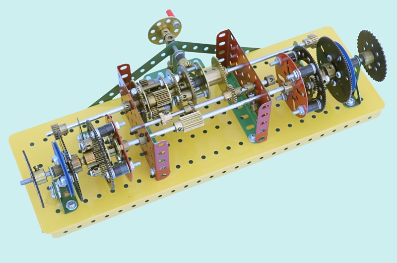
Figure 3 First attempt at building the transmission
The bevel gear input is replaced with a 57-tooth gear to the differential. A simple 3-speed input/output shaft is arranged to mesh through 1:1 gearing with the differential cage. The layshaft is located above this which includes a link to a sliding 25-tooth contrate gear on the main output shaft. This contrate can engage a 25-tooth pinion fixed to the main output shaft to lock the latter and the gearbox output, thereby selecting reverse via the three differentials.
The differential half shafts carry a train of three 19-tooth pinions to maintain correct direction of rotation.
A detent selector and lever were added for gear shift control and a cord brake and lever to the left hand side only to demonstrate steering control.
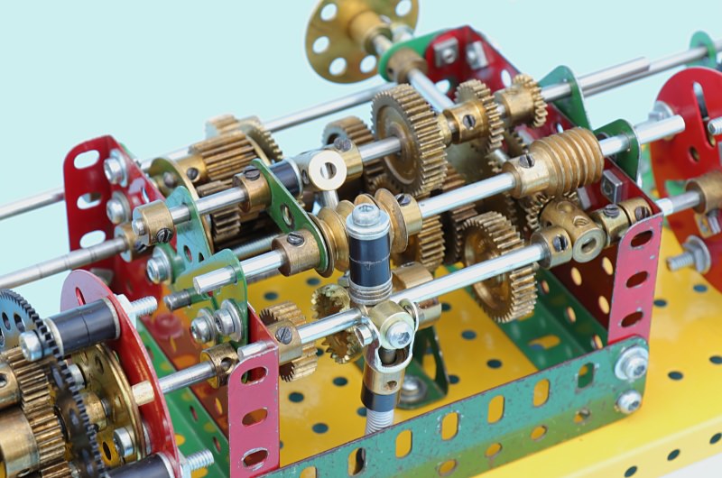
Figure 4 Detent selector and lever
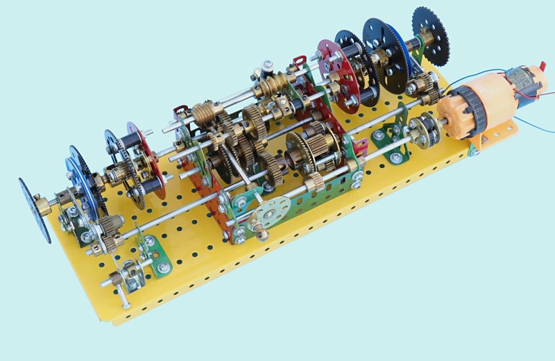
Figure 5 Cord brake and lever (lower left)
The PDU slave motor enables the gearbox drive and steering modes to be analysed dynamically, although its position parallel to the gearbox is not prototypical.
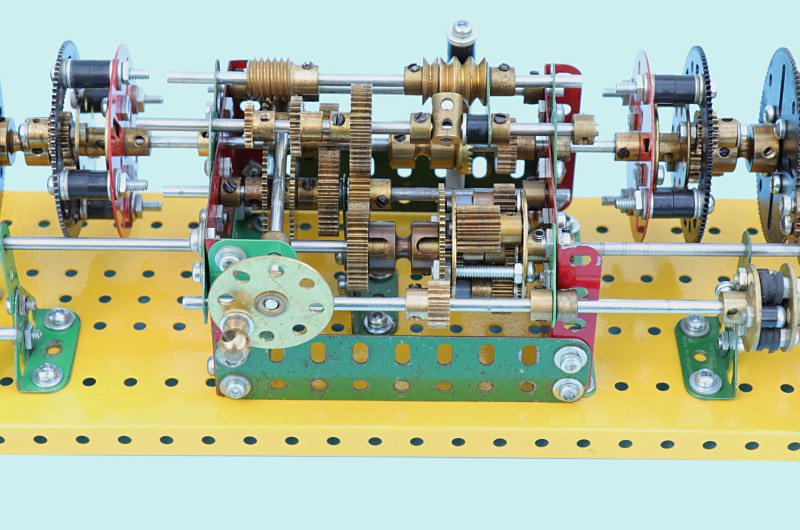
Figure 6 Close-up view of gearbox
The table below is a spreadsheet analysis of drive and steering modes to document the data and calculate respective ratios. The calculations are based on H. E. Merritt method 6.4.4 from ‘GEAR TRAINS’ with nomenclature changes for single epicyclic case III; Ns and Na. All functions were checked physically and agreed with the calculated values. Note that carrier ≡ sprocket.
Further Development
Several issues were realised in running the transmission under power, some of which were due to drag produced by the components connected with Socket Couplings. Another was due to alignment of the planet gears within the Ring Gears. These aftermarket Ring Gears are not designed and manufactured correctly — the internal teeth are cut to size, leaving no clearance for proper running (i.e. backlash). This is easily shown when using a plastic 57-tooth gear positioned within the internal teeth of the Ring Gears when setting up for concentricity — the 57-tooth gear is a tight fit! Also, the input differential jumped teeth under load indicating the need for better support.
As referred to earlier, the drive to the input differential is not realistic of actual practice, so another attempt at a right angle drive was desirable.
These issues were overcome by the following:
- Dispensed with securing bosses into the Socket Coupling with Grub Screws by using Shoulder Bolts screwed into the bossed components and engaging these with the grooves in the Socket Couplings.
- Arranging for the Ring Gears to ‘float’ by mounting them freely via their ra-dial slotted holes.
- Adding an additional bearing close to the drive side of the input differential.
- Devising a method for engaging a narrow-face 38-tooth gear with the non-bossed face of a 48-tooth Bevel Gear, achieved by extending two Screwed Rods through the toothed side of the Bevel Gear.
These changes greatly improved the free running of the transmission and resulted in a more robust unit.
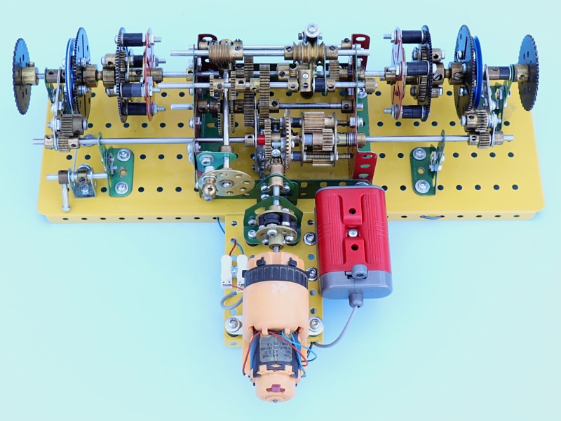
Figure 7 The revised transmission
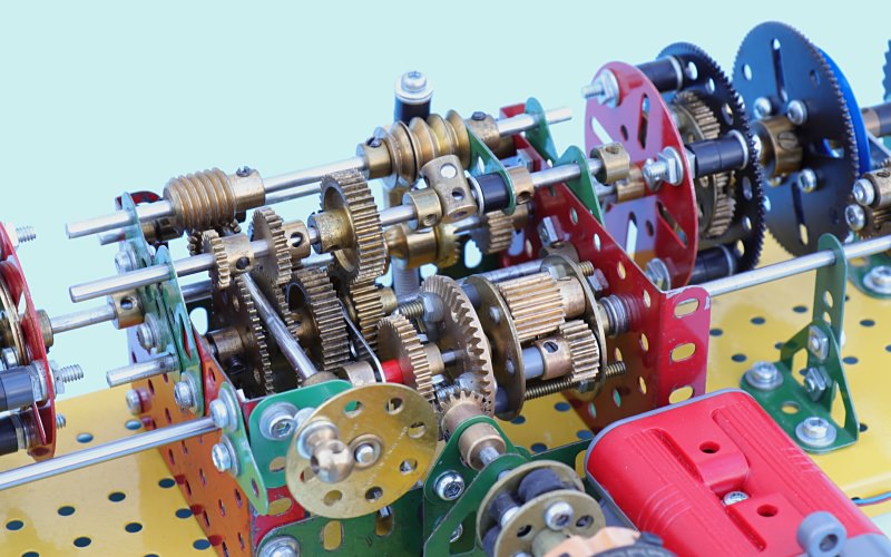
Figure 8 Close-up view of revised gearbox
I was intrigued to know how this transmission schematic was engineered, particularly with respect to the steering drum and output epicyclic train quill shaft configuration.
A search of the internet led to two cutaway and sectional views (figures 9 and 10) which show the construction in good detail.
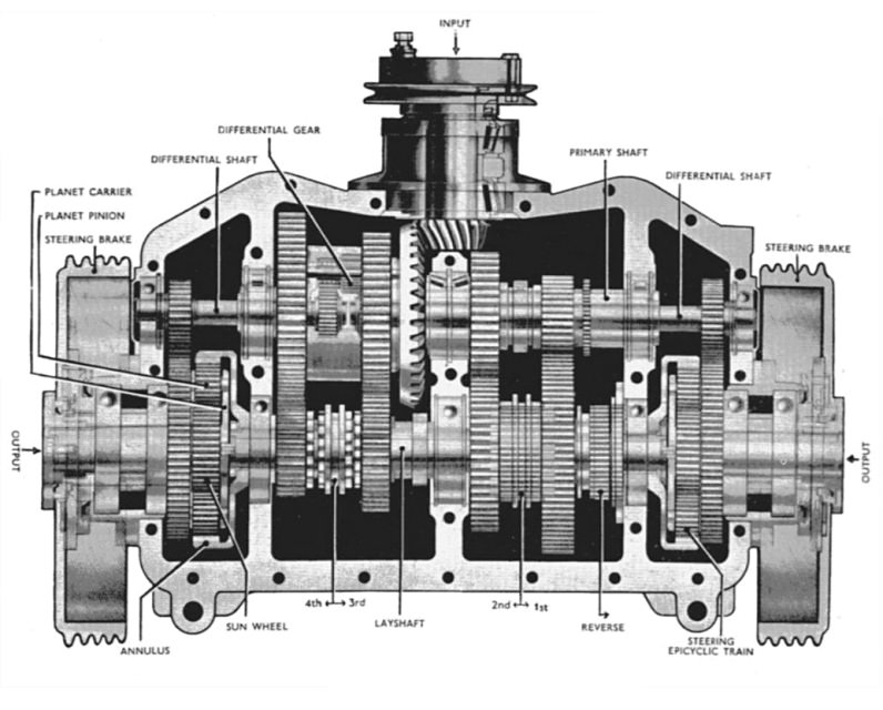
Figure 9 Cutaway view of TN.12 transmission
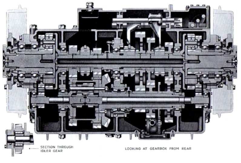
Figure 10 Sectional view of TN.12 transmission
Summary
This is an interesting transmission, although complicated by having the gearbox between the steering epicyclics. In retrospect, an easier system to model is the triple differential layouts used on earlier tanks prior to the use of the Merritt-Brown versions (figure 11, reference 3). This arrangement facilitates a conventional in-line engine-gearbox and right angle (bevel gear driven) input differential.
This should perform exactly as the Merritt-Brown version and allows much greater freedom and flexibility in the type of gearbox employed.
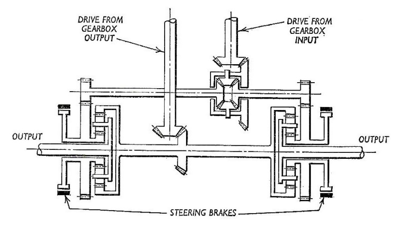
Figure 11 Alternative triple differential layout
Conclusions
I have found that the best traction and steering control for a tracklaying model is the double differential system, under radio control, as in my M4 High-Speed Tractor. With this system the steering function is infinitely variable and affords control equivalent to that of a wheeled vehicle.
The next best controllable track-laying system is probably the Cletrac.
References
- Merritt, H. E. “The Evolution of a Tank Transmission.” Proceedings of the Institute of Mechanical Engineers, volume 154, issue 1, 1946.
- Montgomery, Nigel. Churchill Tank Owners’ Workshop Manual. Haynes, 2013.
- Ogorkiewicz, Richard. Design and Development of Fighting Vehicles. Doubleday, 1968.